725rE 2-Cycle Gas Trimmer / Edger OPERATOR’S MANUAL T r i m m e r P lus ® FOR QUESTIONS, CALL 1-800-345-8746 in U.S. or 1-800-265-6778 in CANADA www.ryobi.
INTRODUCTION TABLE OF CONTENTS THANK YOU I. California Emission Regulations . . . . . . . . . . . . . . . . . 3 Thank you for buying this quality product. This modern outdoor power tool will provide many hours of useful service. You will find it to be a great labor-saving device. This operator’s manual provides you with easy-to-understand operating instructions. Read the whole manual and follow all the instructions to keep your new outdoor power tool in top operating condition.
CALIFORNIA EMISSION REGULATIONS This unit meets the 1995 to 1998 California emissions regulations for small off-road engines. These units are identified by the label on the engine of your product. A typical identification label is shown. To ensure that your unit continues to meet these regulations, refer to the following information and instructions in this operator’s manual.
RULES FOR SAFE OPERATION • IMPORTANT SAFETY INFORMATION • READ ALL INSTRUCTIONS • Read the instructions carefully. Be familiar with the controls and proper use of the unit. • Mix and add fuel in a clean, well-ventilated area outdoors where there are no sparks or flames. Slowly remove the fuel cap only after stopping engine. Do not smoke while fueling or mixing fuel. Wipe up any spilled fuel from the unit immediately.
RULES FOR SAFE OPERATION • Do not touch the engine or muffler. These parts get extremely hot from operation. When turned off they remain hot for a short time. • Do not operate the engine faster than the speed needed to cut, trim or edge. Do not run the engine at high speed when not cutting. • Always stop the engine when cutting is delayed or when walking from one cutting location to another. • If you strike or become entangled with a foreign object, stop the engine immediately and check for damage.
RULES FOR SAFE OPERATION SAFETY AND INTERNATIONAL SYMBOLS This operator's manual describes safety and international symbols and pictographs that may appear on this product. Read the operator's manual for complete safety, assembly, operating and maintenance and repair information. SYMBOL MEANING • SAFETY ALERT SYMBOL Indicates danger, warning, or caution. May be used in conjunction with other symbols or pictographs.
RULES FOR SAFE OPERATION SYMBOL MEANING • HOT SURFACE WARNING Do not touch a hot muffler or cylinder. You may get burned. These parts get extremely hot from operation. When turned off they remain hot for a short time. • SHARP BLADE WARNING: There is a sharp blade on the cutting attachment shield. To prevent serious injury, do not touch blade. • INDICATES OIL Refer to operator's manual for the proper type of oil. • CHOKE CONTROL A • FULL CHOKE position. B • PARTIAL CHOKE position. C • RUN position.
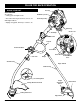
RULES FOR SAFE OPERATION KNOW YOUR UNIT Fuel Cap APPLICATIONS As a trimmer; • Cutting grass and light weeds. On/Off Stop Control • Decorative trimming around trees, fences, etc. Starter Rope Grip With Edger Add-On; • Edging along paths, driveways, rockeries, etc.
ASSEMBLY INSTRUCTIONS INSTALLING AND ADJUSTING THE J-HANDLE 1. Place the J-handle between the top and middle clamp pieces (Fig. 1). 6. While holding the unit in the operating position (Fig. 3), position the J-handle to the location that provides you the best grip. J-Handle (4) Screws Top Clamp Middle Clamp Bottom Clamp Nuts Fig. 1 2. While holding the three pieces together, install the four (4) screws through the top clamp and into middle clamp.
OIL AND FUEL INFORMATION OIL AND FUEL MIXING INSTRUCTIONS Old and/or improperly mixed fuel are the main reasons for the unit not running properly. Be sure to use fresh, clean unleaded fuel. Follow the instructions carefully for the proper fuel/oil mixture. Definition of Blended Fuels Today's fuels are often a blend of gasoline and oxygenates such as ethanol, methanol or MTBE (ether). Alcohol-blended fuel absorbs water. As little as 1% water in the fuel can make fuel and oil separate.
STARTING/STOPPING INSTRUCTIONS STARTING INSTRUCTIONS WARNING: Avoid accidental starting. Be in the starting position when pulling the starter rope (Fig. 6). The operator and unit must be in a stable position while starting to avoid serious personal injury. Avoid serious personal injury, ensure any Add-On being used is installed correctly and secure before starting unit. 5. With the unit on the ground, squeeze the throttle control and pull starter rope briskly (Fig. 6).
OPERATING INSTRUCTIONS OPERATING THE CLICK-LINK® SYSTEM Click-Link® The system enables the use of these optional add-ons. Blower/Vacuum . . . . . . . . . . . . . . . . . . . . . . . . . . BV720r Cultivator . . . . . . . . . . . . . . . . . . . . . . . . . . . . . . GC720r Hedge Trimmer . . . . . . . . . . . . . . . . . . . . . . . . . . HS720r Snow Thrower . . . . . . . . . . . . . . . . . . . . . . . . . . . ST720r Straight Shaft Trimmer (SpeedSpool®) . . . . . . . . SS725r Tree Pruner . . . . . . . . . .
OPERATING INSTRUCTIONS HOLDING THE TRIMMER WARNING: Always wear eye, hearing, foot and body protection to reduce the risk of injury when operating this unit. Before operating the unit, stand in the operating position (Fig. 10). Check for the following: • The operator is wearing eye protection and proper clothing. • The right arm is slightly bent, and the hand is holding the shaft grip. • The left arm is straight, and the hand is holding the handle. • The unit is at waist level.
OPERATING INSTRUCTIONS DECORATIVE TRIMMING Decorative trimming is accomplished by removing all vegetation around trees, posts, fences, etc. Rotate the whole unit so that the cutting attachment is at a 30° angle to the ground (Fig. 12). HOLDING THE UNIT WITH EDGER ADD-ON WARNING: Always wear eye, hearing, foot and body protection to reduce the risk of injury when operating this unit. Before operating the unit, stand in the operating position (Figs. 13).
OPERATING INSTRUCTIONS ADJUSTING EDGER CUTTING DEPTH HANGER 1. Loosen the adjustment knob above the wheel (Fig 14). 2. Slide the wheel to the desired position. • Raising the wheel increases the cutting depth. • Lowering the wheel decreases the cutting depth. 3. Tighten the adjustment knob securely. A plastic hanger (Fig. 15) comes attached to the end of the add-on shaft housing. Use it to hang up the edger, cutting attachment, or other add-on out of the way when not in use.
MAINTENANCE AND REPAIR INSTRUCTIONS LINE INSTALLATION FOR THE SPEEDSPOOL® Always use genuine Ryobi 0.080 in. (2.03 mm.) replacement line. Larger line may make the engine overheat or fail. WARNING: Never use metal-reinforced line, wire, or rope, etc.. These can break off and become a dangerous projectile. There are two methods to replace the SpeedSpool® trimming line.
MAINTENANCE AND REPAIR INSTRUCTIONS 7. Repeat procedures 4-6 with the second piece of line. 8. Hold the outer spool. Wind the inner reel counterclockwise until approximately four (4) inches (102 mm.) of line remain (Fig. 20). NOTE: Do not wind the inner reel before installing the second piece of line. Installing a Prewound Inner reel 1. Turn the Bump Knob counterclockwise and remove the bump knob, spring, and foam seal (Fig. 22). Bump Knob Foam Seal Spring Inner Reel Fig. 22 Fig. 20 9.
MAINTENANCE AND REPAIR INSTRUCTIONS Cleaning the SpeedSpool® Cleaning the SpeedSpool® may be necessary, • To remove jammed or excess line, • If the SpeedSpool® becomes difficult to wind or does not operate correctly when bumping the head on the ground, 1. Hold the outer spool, and unscrew the bump knob counterclockwise (Fig. 24). 5. Clean the shaft and the inner surface of the outer spool. To clean the shaft underneath the plunger, press down on the plunger (Fig. 26).
MAINTENANCE AND REPAIR INSTRUCTIONS EDGER BLADE REPLACEMENT WARNING: To avoid serious personal injury, always wear gloves while handling, removing or installing the blade. 3. Install the new blade, blade retainer, and nut (Fig. 29). Edger Blade Blade Retainer WARNING: The gear housing gets hot after long periods of use. To avoid serious personal injury, do not touch the housing until it has cooled. Lock Nut 1. Line up the hole in output shaft with the locking rod slot.
MAINTENANCE AND REPAIR INSTRUCTIONS AIR FILTER MAINTENANCE Removing the Air Filter/Muffler Cover WARNING: To avoid serious personal injury, always turn your trimmer off and allow it to cool before you clean or do any maintenance on it. 1. Place the choke lever in the PARTIAL choke position (B). Air Filter NOTE: The choke lever must be in the PARTIAL choke position (B) (Fig. 31) to remove the air filter/muffler cover. 2. Remove the four (4) screws securing the air filter/muffler cover (Fig. 31).
MAINTENANCE AND REPAIR INSTRUCTIONS 5. Squeeze the filter to spread and remove excess oil (Fig. 35). If after checking the fuel mixture and cleaning the air filter the engine still will not idle, adjust the idle speed screw as follows. 1. Start the engine and let it run at a high idle for a minute to warm up. See Starting/Stopping Instructions, Pg. 11. 2. Release the throttle trigger and let the engine idle.
MAINTENANCE AND REPAIR INSTRUCTIONS REPLACING THE SPARK PLUG Use a Champion RDJ7Y spark plug (or equivalent). The correct air gap is 0.020 inch (0.5 mm.). Remove the plug after every 50 hours of operation and check its condition. 1. Stop the engine and allow it to cool. Grasp the plug wire firmly and pull it from the spark plug. 2. Clean around the spark plug. Remove the spark plug from the cylinder head by turning a 5/8 in. socket counterclockwise. 3. Replace cracked, fouled or dirty spark plug.
CLEANING AND STORAGE CLEANING WARNING: To avoid serious personal injury, always turn your trimmer off and allow it to cool before you clean or do any maintenance on it. Use a small brush to clean off the outside of the unit. Do not use strong detergents. Household cleaners that contain aromatic oils such as pine and lemon, and solvents such as kerosene, can damage plastic housing or handle. Wipe off any moisture with a soft cloth. TRANSPORTING • Allow the engine to cool before transporting.
TROUBLESHOOTING ENGINE WILL NOT START CAUSE ACTION On/Off Stop Control is in OFF position Turn On/Off Stop Control to ON Empty fuel tank Fill fuel tank with properly mixed fuel Primer bulb wasn't pressed enough Press primer bulb fully and slowly 5-7 times Engine flooded Use starting procedure with choke lever in the RUN position, Pg.
SPECIFICATIONS ENGINE Engine Type . . . . . . . . . . . . . . . . . . . . . . . . . . . . . . . . . . . . . . . . . . . . . . . . . . . . . . . . . . . . . . . . . Air-Cooled, 2-Cycle Stroke . . . . . . . . . . . . . . . . . . . . . . . . . . . . . . . . . . . . . . . . . . . . . . . . . . . . . . . . . . . . . . . . . . . . . . 1.25 in. (31.75 mm.) Displacement . . . . . . . . . . . . . . . . . . . . . . . . . . . . . . . . . . . . . . . . . . . . . . . . . . . . . . . . . . . . . . . . . . 1.9 cu in.
NOTES 26
CALIFORNIA EMISSION CONTROL WARRANTY STATEMENT YOUR WARRANTY RIGHTS AND OBLIGATIONS The California Air Resources Board and Ryobi Outdoor Products (ROP), are pleased to explain the emission control system warranty on your 1995 and later small off-road engine. In California, new small off-road engines must be designed, built and equipped to meet the State's stringent anti-smog standards.
LIMITED TWO-YEAR WARRANTY RYOBI OUTDOOR PRODUCTS warrants each new RYOBI Product for two (2) years according to the following terms. This warranty extends to the original retail purchaser only and commences on the date of original retail purchase. Any part of the RYOBI Product manufactured or supplied by RYOBI and found in the reasonable judgement of RYOBI to be defective in material or workmanship will be repaired or replaced by an authorized RYOBI service dealer without charge for parts and labor.