OPERATOR’S MANUAL 10 in. TABLE SAW BTS10 Your table saw has been engineered and manufactured to Ryobi’s high standard for dependability, ease of operation, and operator safety. When properly cared for, it will give you years of rugged, trouble-free performance. WARNING: To reduce the risk of injury, the user must read and understand the operator's manual before using this product. Thank you for buying a Ryobi product.
TABLE OF CONTENTS n Introduction ..................................................................................................................................................................... 2 �n General Safety Rules .................................................................................................................................................... 3-4 �n Specific Safety Rules..............................................................................................................
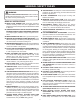
GENERAL SAFETY RULES n SECURE WORK. Use clamps or a vise to hold work when practical. It’s safer than using your hand and frees both hands to operate tool. WARNING: Read and understand all instructions. Failure to follow all instructions listed below, may result in electric shock, fire and/or serious personal injury. n DON’T OVERREACH. Keep proper footing and balance at all times. n MAINTAIN TOOLS WITH CARE. Keep tools sharp and clean for better and safer performance.
GENERAL SAFETY RULES n n n n n n n n n work or around or over the blade while blade is rotating. Do not attempt to remove cut material when blade is moving. BLADE COASTS AFTER BEING TURNED OFF. NEVER USE IN AN EXPLOSIVE ATMOSPHERE. Normal sparking of the motor could ignite fumes. INSPECT TOOL CORDS PERIODICALLY. If damaged, have repaired by a qualified service technician at an authorized service facility.
SPECIFIC SAFETY RULES n NEVER perform any operation “freehand” which means using only your hands to support or guide the workpiece. Always use either the rip fence or miter fence to position and guide the work. n NEVER stand or have any part of your body in line with the path of the saw blade. n NEVER reach behind, over, or within three inches of the blade or cutter with either hand for any reason. n MOVE THE RIP FENCE out of the way when cross cutting.
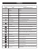
SYMBOLS Some of the following symbols may be used on this tool. Please study them and learn their meaning. Proper interpretation of these symbols will allow you to operate the tool better and safer.
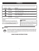
SYMBOLS The following signal words and meanings are intended to explain the levels of risk associated with this product. SYMBOL SIGNAL MEANING DANGER: Indicates an imminently hazardous situation, which, if not avoided, will result in death or serious injury. WARNING: Indicates a potentially hazardous situation, which, if not avoided, could result in death or serious injury. CAUTION: Indicates a potentially hazardous situation, which, if not avoided, may result in minor or moderate injury.
ELECTRICAL SPEED AND WIRING EXTENSION CORDS The no-load speed of this tool is approximately 4,800 rpm. This speed is not constant and decreases under a load or with lower voltage. For voltage, the wiring in a shop is as important as the motor’s horsepower rating. A line intended only for lights cannot properly carry a power tool motor. Wire that is heavy enough for a short distance will be too light for a greater distance.
GLOSSARY OF TERMS Anti-Kickback Pawls (radial arm and table saws) A device which, when properly installed and maintained, is designed to stop the workpiece from being kicked back toward the front of the saw during a ripping operation. Arbor The shaft on which a blade or cutting tool is mounted. Bevel Cut A cutting operation made with the blade at any angle other than 90° to the table surface. Chamfer A cut removing a wedge from a block so the end (or part of the end) is angled rather than at 90°.
FEATURES PRODUCT SPECIFICATIONS Blade Diameter..........................................................10 in. Blade Arbor ..............................................................5/8 in. Cutting Depth at 0°......................................................3 in. Cutting Depth at 45°............................................. 2-1/2 in. TOOL STORAGE BLADE GUARD ASSEMBLY SPREADER Table Size ...............................................25-3/4 in. x 16 in. Input .............................
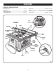
FEATURES KNOW YOUR TABLE SAW BLADE - This saw comes with a 10 in, 24-tooth blade. The blade is adjusted with bevel adjusting handwheel on the front of the cabinet. Bevel angles are locked with a bevel lock lever below the front rail. See Figure 2. Before attempting to use this product, familiarize yourself with all operating features and safety rules. OVERVIEW WARNING: The upper portion of the blade projects up through the table, surrounded by an insert called the throat plate.
FEATURES BLADES WARNING: For maximum performance, it is recommended that you use the 10 in., 24-tooth blade provided with your saw. Additional blade styles of the same high quality are available for specific operations such as ripping. Your local dealer can provide you with complete information. ALWAYS make sure your workpiece is not in contact with the blade before operating the switch to start the tool.
TOOLS NEEDED The following tools (not included) are needed for assembly and making adjustments: WRENCH (2) 10 mm, 11 mm PHILLIPS SCREWDRIVER FLATHEAD SCREWDRIVER FRAMING SQUARE Fig.
LOOSE PARTS LIST 2 1 6 3 4 13 14 11 5 15 12 17 14 16 7 9 8 10 Fig. 5 Key No. Description 1 2 3 4 5 6 7 8 9 10 11 12 13 14 15 16 17 18 19 Blade Guard Assembly......................................................................................................................................1 Lock Nut ............................................................................................................................................................1 Blade Adjusting Handle..............
ASSEMBLY UNPACKING MOUNTING HOLES This product requires assembly. n Carefully remove the tool and any accessories from the box. Place it on a level work surface. n Inspect the tool carefully to make sure no breakage or damage occurred during shipping. n Do not discard the packing material until you have carefully inspected the tool, identified all loose parts, and satisfactorily operated the tool. n If any parts are damaged or missing, please call 1-800525-2579 for assistance.
ASSEMBLY TO REMOVE/REPLACE THE THROAT PLATE REMOVING THE THROAT PLATE See Figure 7. n Lower the blade by turning the height adjusting handwheel clockwise. SCREW THROAT PLATE n Loosen the screws in the throat plate. SPACER SPACER n Lift the throat plate and spacers from the saw. n To reinstall the throat plate, place the spacers of the holes and align the holes in the throat plate with the holes in the saw housing.
ASSEMBLY If the spreader and saw blade are not in alignment, adjustment is needed. To adjust: WARNING: n Unplug the saw then raise the blade guard assembly. It is important to install and adjust the blade guard assembly correctly. Poor alignment could cause kickback and throw the workpiece at the operator. n Loosen the socket head cap screws holding the blade guard assembly to the mounting bracket. n Reposition the blade guard assembly left or right as needed to align the spreader with the saw blade.
OPERATION n n n n WARNING: Do not allow familiarity with tools to make you careless. Remember that a careless fraction of a second is sufficient to inflict serious injury. Not following correct operating procedures Misusing the saw Failing to use the anti-kickback pawls Cutting with a dull, gummed-up, or improperly set blade AVOIDING KICKBACK You may use this tool for the purposes listed below: n Straight line cutting operations such as cross cutting, ripping, mitering, beveling, and compound cutting.
OPERATION TYPES OF CUTS See Figure 13. There are six basic cuts: 1) the cross cut, 2) the rip cut, 3) the miter cut, 4) the bevel cross cut, 5) the bevel rip cut, and 6) the compound (bevel) miter cut. All other cuts are combinations of these basic six. Operating procedures for making each kind of cut are given later in this section. 1 CROSS CUT WARNING: Always make sure the blade guard and anti-kickback pawls are in place and working properly when making these cuts to avoid possible injury.
OPERATION FEATHERBOARD HOW TO MOUNT A FEATHERBOARD A featherboard is a device used to help control the workpiece by guiding it securely against the table or rip fence. Featherboards are especially useful when ripping small workpieces and for completing non-through cuts. The end is angled, with a number of short kerfs to give a friction hold on the workpiece. Lock it in place on the table with a C-clamp. Test that it can resist kickback by restricting the forward motion of the workpiece. See Figure 15.
OPERATION TO ADJUST THE BLADE DEPTH GULLET See Figure 16. The blade depth should be set so that the outer tips of the blade are higher than the workpiece by approximately 1/8 in. to 1/4 in. but the lowest points (gullets) are below the top surface. Raise the blade by turning the height adjusting handwheel counterclockwise or lower it by turning the handle clockwise. TO ADJUST THE BEVEL ANGLE See Figure 17.
OPERATION RIP FENCE WARNING: To reduce the risk of injury, always make sure the rip fence is parallel to the blade before beginning any operation. TO INSTALL THE RIP FENCE See Figure 19. n Place the rear lip on the rear of the saw table and pull slightly toward the front of the unit. n Lower the front end of the rip fence onto the guide surfaces on top of the front rail. n Push the rip fence lever down to automatically align and secure the fence. The trigger lock must engage.
OPERATION MAKING CUTS of injury should kickback occur. Keep the miter gauge firmly against the saw table as the workpiece is fed into the blade. NOTE: The hand closest to the blade should be placed on the miter gauge lock knob and the hand farthest from the blade should be placed on the miter gauge and the workpiece. n When the cut is made, turn the saw OFF. Wait for the blade to come to a complete stop before removing any part of the workpiece.
OPERATION TO MAKE A MITER CUT n Let the blade build up to full speed before feeding the workpiece into the blade. n Use a push block or push stick to move the wood through the cut past the blade. Never push a small piece of wood into the blade with your hand, always use a push stick. The use of push blocks, push sticks, and featherboards are necessary when making non-through cuts. n Stand to the side of the wood as it contacts the blade to reduce the chance of injury should kickback occur.
OPERATION TO MAKE A BEVEL CROSS CUT n Remove the miter gauge by sliding it out of the miter gauge groove. See Figure 26. n Turn the bevel locking lever to the left to unlock. Turn the height adjusting handle until the bevel indicator is at the desired angle. n Set the blade to the correct depth for the workpiece and push the bevel locking lever to the right to relock it. WARNING: Make sure the blade guard assembly is installed and working properly to avoid serious personal injury.
OPERATION n Position the rip fence the desired distance from the right side of the blade and lock down the lever. n If ripping a piece larger than 36 in. long, place a support the same height as the table surface behind the saw for the cut work. n Make sure the wood is clear of the blade before turning on the saw. n Turn the saw ON. n Position the workpiece flat on the table with the edge flush against the rip fence. Let the blade build up to full speed before feeding the workpiece into the blade.
OPERATION Once all non-through cuts are complete: n Unplug the saw. n Lower the blade and reinstall the blade guard assembly using the two socket head cap screws, lock washers, and flat washers. TO MAKE A NON-THROUGH CUT See Figure 29. Non-through cuts can be made with the grain (ripping) or across the grain (cross cut). The use of a non-through cut is essential to cutting grooves and rabbets. DO NOT perform bevel non-through cuts on this machine.
OPERATION TO MAKE DADO CUTS n When mounting dado blades, make sure both the inner blade washer and outer blade washer are used. A dado is a non-through cut and typically refers to a channel cut, both with the grain and across the grain. (The Ryobi part number for the dado set is 4650306.) DO NOT perform bevel dado cuts on this machine. n Replace the throat plate with the optional Dado Throat Plate (#0131030330-35). When ordering parts, always give the model number. Call 1-800-525-2579 for assistance.
ADJUSTMENTS TO SET THE 90° POSITIVE STOP 90° POSITIVE STOP ADJUSTMENT SCREW See Figure 31. Make sure the saw is unplugged from the power source. Raise the blade to the maximum height by turning the height adjusting handwheel counterclockwise. Unlock the bevel locking lever. Next, push the height adjusting handwheel in toward the saw and rotate clockwise until it stops. Use the framing square to check the position of the blade. Relock the bevel locking lever.
MAINTENANCE TO REMOVE OR CHANGE THE BLADE WARNING: See Figure 33. n Raise the blade to the maximum height. n Remove the screws and rubber spacers holding the throat plate in place then remove the throat plate. n To keep blade arbor from rotating, place the open ended wrench on flats located on the left side of the blade. n Place the second wrench over the arbor nut located on the right side of the blade. Turn nut counterclockwise to loosen. n Remove arbor nut and outer blade washer.
TROUBLESHOOTING Problem Excess Vibration. Possible Cause 1. Blade is out of balance. 2. Blade is warped or damaged. 3. Saw is not mounted securely to a level work surface. Rip fence does not operate smoothly. 1. Rip fence not mounted correctly. Solution 1. Remount and recheck blade. Replace if necessary. 2. Replace blade immediately. 3. Reposition on a level surface and tighten all mounting hardware securely. 3. Adjustment nut needs adjusting. 1. Remount the rip fence. 2.
OPERATOR’S MANUAL 10 in. TABLE SAW BTS10 • SERVICE Now that you have purchased your tool, should a need ever exist for repair parts or service, simply contact your nearest Ryobi Authorized Service Center. Be sure to provide all pertinent facts when you call or visit. Please call 1-800-525-2579 for your nearest Ryobi Authorized Service Center. You can also check our web site at www.ryobitools.com for a complete list of Authorized Service Centers. • MODEL NO. AND SERIAL NO.