OPERATOR’S MANUAL 7-1/4 in. CIRCULAR SAW DOUBLE INSULATED CSB122 Your circular saw has been engineered and manufactured to our high standard for dependability, ease of operation, and operator safety. When properly cared for, it will give you years of rugged, trouble-free performance. WARNING: To reduce the risk of injury, the user must read and understand the operator’s manual before using this product. Thank you for your purchase.
TABLE OF CONTENTS Introduction...................................................................................................................................................................... 2 Warranty........................................................................................................................................................................... 2 General Safety Rules........................................................................................................
GENERAL SAFETY RULES Keep your work area clean and well lit. Cluttered benches and dark areas invite accidents. Do not operate power tools in explosive atmospheres, such as in the presence of flammable liquids, gases, or dust. Power tools create sparks which may ignite the dust or fumes. Keep bystanders, children, and visitors away while operating a power tool. Distractions can cause you to lose control. Avoid accidental starting. Be sure switch is off before plugging in.
GENERAL SAFETY RULES SERVICE When servicing a tool, use only identical replacement parts. Follow instructions in the Maintenance section of this manual. Use of unauthorized parts or failure to follow Maintenance Instructions may create a risk of electric shock or injury. Tool service must be performed only by qualified repair personnel. Service or maintenance performed by unqualified personnel could result in a risk of injury.
SPECIFIC SAFETY RULES Support large panels to minimize the risk of blade pinching and kickback. Large panels tend to sag under their own weight. Supports must be placed under the panel on both sides, near the line of cut and near the edge of the panel. Constantly stay aware of cord location. Following this rule will reduce the risk of electric shock or fire. Check damaged parts.
SYMBOLS Some of the following symbols may be used on this product . Please study them and learn their meaning. Proper interpretation of these symbols will allow you to operate the product better and safer.
SYMBOLS The following signal words and meanings are intended to explain the levels of risk associated with this product. SYMBOL SIGNAL MEANING DANGER: Indicates an imminently hazardous situation, which, if not avoided, will result in death or serious injury. WARNING: Indicates a potentially hazardous situation, which, if not avoided, could result in death or serious injury. CAUTION: Indicates a potentially hazardous situation, which, if not avoided, may result in minor or moderate injury.
ELECTRICAL DOUBLE INSULATION EXTENSION CORDS Double insulation is a concept in safety in electric power tools, which eliminates the need for the usual threewire grounded power cord. All exposed metal parts are isolated from the internal metal motor components with protecting insulation. Double insulated tools do not need to be grounded.
FEATURES PRODUCT SPECIFICATIONS Blade Diameter.......................................................7-1/4 in. Cutting Depth at 51.5º............................................1-5/8 in. Blade Arbor............................................................... 5/8 in. No Load Speed..................................... 4,600 r/min. (RPM) Cutting Depth at 0º.................................................2-3/8 in. Input.................................
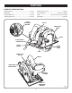
FEATURES KNOW YOUR CIRCULAR SAW SPINDLE LOCK See Figure 1. The safe use of this product requires an understanding of the information on the product and in this operator’s manual as well as a knowledge of the project you are attempting. Before use of this product, familiarize yourself with all operating features and safety rules. The spindle lock allows you to secure the blade when turning the blade screw. NOTE: Do not run circular saw with spindle lock engaged.
ASSEMBLY SPINDLE WARNING: A 7-1/4 in. blade is the maximum blade capacity of the saw. Also, never use a blade that is too thick to allow outer blade washer to engage with the flat on the spindle. Larger blades will come in contact with the blade guards, while thicker blades will prevent blade screw from securing blade on spindle. Either of these situations could result in a serious accident.
ASSEMBLY REMOVING BLADE SPINDLE LOCK BUTTON See Figure 4. Unplug the saw. Depress spindle lock button. Remove blade screw by turning it counterclockwise with the blade wrench. Remove spring washer and outer blade washer (“D” washer). Lift lower blade guard. Remove blade. BLADE SCREW Blade wrench Fig. 4 OPERATION KICKBACK WARNING: See Figures 5 - 8. Kickback occurs when the blade stalls rapidly and the saw is driven back towards you.
OPERATION To lessen the chance of kickback: Keep the blade at the correct depth setting. The depth setting should not exceed 1/4 in. below the material being cut. Inspect the workpiece for knots or nails before cutting. Never saw into a knot or nail. Make straight cuts. Always use a straight edge guide when rip cutting. This helps prevent twisting the blade. KICKBACK - BLADE SET TOO DEEP Use clean, sharp, and properly set blades. Never make cuts with dull blades. Fig.
OPERATION BLADE GUARD SYSTEM See Figure 9. The lower blade guard attached to the circular saw is there for your protection and safety. Do not alter it for any reason. If it becomes damaged, do not operate the saw until you have the guard repaired or replaced. Always leave guard in operating position when using the saw. DANGER: When sawing through work, lower blade guard does not cover blade on the underside of work. Since blade is exposed on underside of work, keep hands and fingers away from cutting area.
OPERATION OPERATING THE SAW See Figures 12 - 14. It is important to understand the correct method for operating the saw. Refer to the figures in this section to learn the correct and incorrect ways for handling the saw. WARNING: To make sawing easier and safer, always maintain proper control of the saw. Loss of control could cause an accident resulting in possible serious injury.
OPERATION CROSS CUTTING/RIP CUTTING TOP VIEW OF SAW See Figures 15 - 16. When making a cross cut or rip cut, align the line of cut with the outer blade guide notch on the base as shown in the figure. Since blade thicknesses vary, always make a trial cut in scrap material along a guideline to determine how much, if any, you must offset the guideline to produce an accurate cut. NOTE: The distance from the line of cut to the guideline is the amount you should offset the guide.
OPERATION BEVEL CUTTING See Figures 17 - 18. To make the best possible cut, follow these helpful hints. Align the line of cut with the inner blade guide notch on the base when making 45° bevel cuts. MOTOR HOUSING Make a trial cut in scrap material along a guideline to determine how much you should offset the guideline on the cutting material. Adjust the angle of the cut to any desired setting between zero and 51.5°. Refer to TO ADJUST BEVEL SETTING next.
OPERATION 0° BEVEL STOP See Figure 19. The saw has a 0° bevel stop that has been factory adjusted to assure 0° angle of the saw blade when making 90° cuts. To check 0° bevel stop: Unplug the circular saw. HEX NUT Place the saw in an upside down position on a workbench. WING NUT Check the squareness of the saw blade plate to the base of the saw using a combination square. CARPENTER’S SQUARE To adjust 0° bevel stop: Unplug the circular saw. Loosen wing nut.
OPERATION POCKET CUTTING See Figure 21. WARNING: LOWER BLADE GUARD Always adjust bevel setting to zero before making a pocket cut. Attempting a pocket cut at any other setting can result in loss of control of the saw possibly causing serious injury. ■ Adjust the bevel setting to zero. Set the blade to the correct blade depth setting. Swing the lower blade guard up using the lower blade guard handle.
OPERATION OPTIONAL RIP GUIDE See Figure 22. Use the optional rip guide, part no. 969862-009, when making long or wide rip cuts with your saw. To assemble rip guide: Unplug the circular saw. Place rip guide through holes in base as shown in the figure. Adjust rip guide to the width needed. Tighten rip guide screw securely. RIP GUIDE SCREW To use rip guide: Secure the workpiece. Position the face of the rip guide firmly against the edge of workpiece.
MAINTENANCE Electric tools used on fiberglass material, wallboard, spackling compounds, or plaster are subject to accelerated wear and possible premature failure because the fiberglass chips and grindings are highly abrasive to bearings, brushes, commutators, etc. Consequently, we do not recommend using this product for extended work on these types of materials. However, if you do work with any of these materials, it is extremely important to clean the product using compressed air.
OPERATOR’S MANUAL 7-1/4 in. CIRCULAR SAW DOUBLE INSULATED CSB122 WARNING: Some dust created by power sanding, sawing, grinding, drilling, and other construction activities contains chemicals known to cause cancer, birth defects or other reproductive harm. Some examples of these chemicals are: • lead from lead-based paints, • crystalline silica from bricks and cement and other masonry products, and • arsenic and chromium from chemically-treated lumber.