OPERATOR'S MANUAL 7-1/4 in. (184 mm) CIRCULAR SAW Model CSB131 DOUBLE INSULATED THANK YOU FOR BUYING A RYOBI CIRCULAR SAW. Your new circular saw has been engineered and manufactured to Ryobi's high standard for dependability, ease of operation, and operator safety. Properly cared for, it will give you years of rugged, trouble-free performance. CAUTION: Carefully read through this entire operator's manual before using your new circular saw.
TABLE OF CONTENTS ■ Introduction ........................................................................................................................................................ 2 ■ General Safety Rules .....................................................................................................................................3-4 ■ Specific Safety Rules ......................................................................................................................................
GENERAL SAFETY RULES ■ WARNING: Read and understand all instructions. Failure to follow all instructions listed below, may result in electric shock, fire and/or serious personal injury. ■ SAVE THESE INSTRUCTIONS WORK AREA ■ ■ ■ Keep your work area clean and well lit. Cluttered benches and dark areas invite accidents. Do not operate power tools in explosive atmospheres, such as in the presence of flammable liquids, gases, or dust. Power tools may create sparks which may ignite the dust or fumes.
GENERAL SAFETY RULES ■ ■ Check for misalignment or binding of moving parts, breakage of parts, and any other condition that may affect the tool’s operation. If damaged, have the tool serviced before using. Many accidents are caused by poorly maintained tools. Use only accessories that are recommended by the manufacturer for your model. Accessories that may be suitable for one tool, may become hazardous when used on another tool.
SPECIFIC SAFETY RULES ■ Kickback is the result of tool misuse and/or incorrect operating procedures or conditions and can be avoided by taking proper precautions, as given below: ■ Maintain a firm grip with both hands on the saw and position your body and arm to allow you to resist KICKBACK forces. KICKBACK forces can be controlled by the operator, if proper precautions are taken.
ADDITIONAL SAFETY RULES Hold tool by insulated gripping surfaces when performing an operation where the cutting tool may contact hidden wiring or its cord. Contact with a “live” wire will make exposed metal parts of the tool “live” and shock the operator. ■ ■ Know your power tool. Read operator’s manual carefully. Learn its applications and limitations, as well as the specific potential hazards related to this tool. Following this rule will reduce the risk of electric shock, fire, or serious injury.
SYMBOLS Important: Some of the following symbols may be used on your tool. Please study them and learn their meaning. Proper interpretation of these symbols will allow you to operate the tool better and safer.
SPECIFICATIONS Blade Diameter Blade Arbor Cutting Depth at 0° Cutting Depth at 45° Cutting Depth at 51.5° Rating Input No Load Speed Net Weight 7-1/4 in. (184 mm) 5/8 in. (16 mm) 2-3/8 in. (60 mm) 1-13/16 in. (46 mm) 1-5/8 in. (41 mm) 120 volts, 60 Hz, AC 13 amperes 5500 RPM 12 lbs. (5.4 kg) UNPACKING INSTRUCTIONS PACKING LIST Your circular saw has been shipped completely assembled. ■ Carefully remove the tool and accessories from the box.
FEATURES DOUBLE INSULATION SWITCH Your Ryobi power tool is double insulated. This means you are separated from the tool's electrical system by two complete sets of electrical insulation. This extra layer of insulation is intended to protect the user from electrical shock due to a break in the wiring insulation. All exposed metal parts are isolated from the internal metal motor components with protecting insulation. Double insulated tools do not need to be grounded.
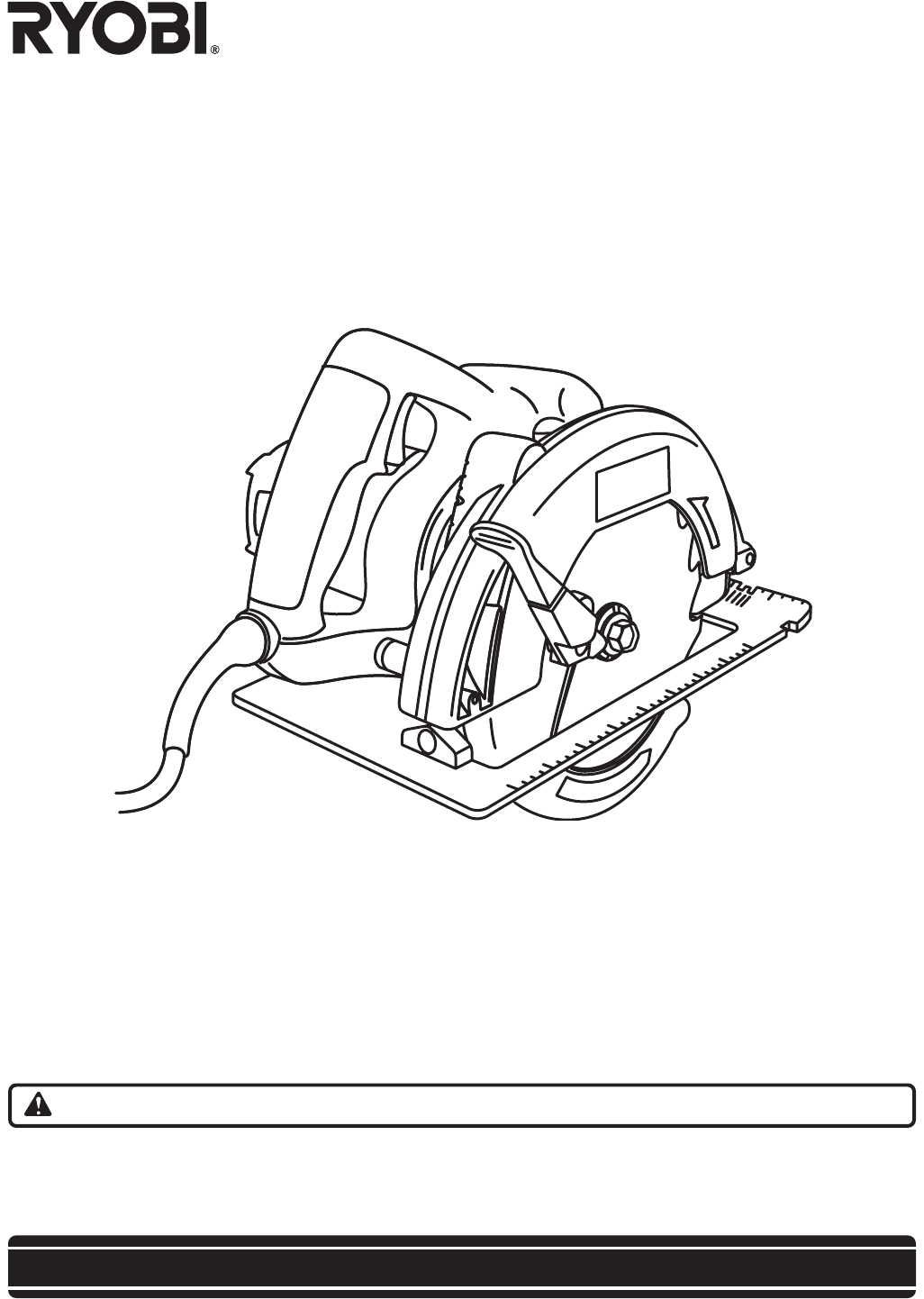
FEATURES SWITCH UPPER BLADE GUARD BLADE DEPTH ADJUSTMENT KNOB LOWER BLADE GUARD BASE HANDLE SPINDLE LOCK BUTTON MOTOR HOUSING LOWER BLADE GUARD HANDLE BEVEL ADJUSTMENT KNOB Fig. 1 WARNING: Do not attempt to modify this tool or create accessories not recommended for use with this tool. Any such alteration or modification is misuse and could result in a hazardous condition leading to possible serious personal injury.
ASSEMBLY WARNING: SPINDLE Your tool should never be connected to power supply when you are assembling parts, making adjustments, cleaning, performing maintenance, or when not in use. Disconnecting your tool will prevent accidental starting that could cause serious injury. BLADE OUTER WASHER (“D” WASHER) WARNING: 7-1/4 in. (184 mm) blade is the maximum blade capacity of your saw. Also, never use a blade that is too thick to allow outer blade washer to engage with the flat on the spindle.
ASSEMBLY REMOVING BLADE SPINDLE LOCK BUTTON See Figure 4. Follow these directions to remove the blade. ■ UNPLUG YOUR CIRCULAR SAW. WARNING: Failure to unplug the tool could result in accidental starting causing serious injury. CAUTION: To prevent damage to the spindle or spindle lock, always allow motor to come to a complete stop before engaging spindle lock. BLADE SCREW WRENCH ■ Depress spindle lock button. ■ Remove blade screw by turning it counterclockwise with the wrench.
OPERATION KICKBACK See Figure 6, 7, 8, and 9. Kickback occurs when the blade stalls rapidly and the saw is driven back towards you. Blade stalling is caused by any action which pinches the blade in the wood. DANGER: Release switch immediately if blade binds or saw stalls. Kickback could cause you to lose control of your saw. Loss of control can lead to serious injury. KICKBACK - BLADE SET TOO DEEP Fig. 6 To guard against kickback, avoid dangerous practices such as the following.
OPERATION STARTING/STOPPING THE SAW See Figure 10. To start the saw: Depress the switch trigger. Always let the blade reach full speed, then guide the saw into the workpiece. SWITCH WARNING: The blade coming in contact with the workpiece before it reaches full speed could cause your saw to “kickback” towards you resulting in serious injury. To stop the saw: Release the switch trigger. After you release the switch trigger, allow the blade to come to a complete stop.
OPERATION OPERATING THE SAW See Figures 12, 13, and 14. It is important to understand the correct method for operating your saw. Refer to the figures in this section to learn the correct and incorrect ways for handling your saw. WARNING: To make sawing easier and safer, always maintain proper control of the saw. Loss of control could cause an accident resulting in possible serious injury.
OPERATION CROSS CUTTING/RIP CUTTING TOP VIEW OF SAW See Figure 15. When making a cross cut or rip cut, align the line of cut with the outer blade guide notch on the base as shown in the figure. Since blade thicknesses vary, always make a trial cut in scrap material along a guideline to determine how much, if any, you must offset the guideline to produce an accurate cut. BLADE GUIDE NOTCH NOTE: The distance from the line of cut to the guideline is the amount you should offset the guideline.
OPERATION BEVEL CUTTING See Figures 17 and 18. To make the best possible cut, follow these helpful hints. ■ Align the line of cut with the inner blade guide notch on the base when making 45° bevel cuts. ■ Make a trial cut in scrap material along a guideline to determine how much you should offset the guideline on the cutting material. ■ Adjust the angle of the cut to any desired setting between zero and 51.5°. Refer to “TO ADJUST BEVEL SETTING” next. TO ADJUST BEVEL SETTING See Figure 17.
OPERATION POSITIVE 0° BEVEL STOP See Figure 19. Your saw has a positive 0° bevel stop, that has been factory adjusted to assure 0° angle of the saw blade when making 90° cuts. However, misalignment can occur during shipping. TO CHECK POSITIVE 0° BEVEL STOP Follow these directions to check the positive 0° bevel stop. ■ UNPLUG YOUR CIRCULAR SAW. BEVEL ADJUSTMENT KNOB SETSCREW WARNING: CARPENTER’S SQUARE Failure to unplug the tool could result in accidental starting causing serious injury.
OPERATION POCKET CUTTING See Figure 21. WARNING: Always adjust bevel setting to zero before making a pocket cut. Attempting a pocket cut at any other setting can result in loss of control of your saw possibly causing serious injury. LOWER BLADE GUARD Follow these directions to pocket cut. ■ Adjust the bevel setting to zero. ■ Set the blade to the correct blade depth setting. ■ Swing the lower blade guard up using the lower blade guard handle.
ACCESSORIES RIP GUIDE Use the rip guide provided, part no. 969862-009, when making long or wide rip cuts with your saw. TO ASSEMBLE RIP GUIDE See Figure 22. Follow these directions to assemble the rip guide. ■ UNPLUG YOUR CIRCULAR SAW. WARNING: RIP GUIDE SCREW Failure to unplug the tool could result in accidental starting causing serious injury. ■ Place rip guide through holes in base as shown in the figure. ■ Adjust rip guide to the width needed. RIP GUIDE ■ Tighten rip guide knob securely.
MAINTENANCE WARNING: When servicing use only identical Ryobi replacement parts. Use of any other parts may create a hazard or cause product damage. GENERAL WARNING: Avoid using solvents when cleaning plastic parts. Most plastics are susceptible to damage from various types of commercial solvents and may be damaged by their use. Use clean cloths to remove dirt, carbon dust, etc. Always wear safety goggles or safety glasses with side shields during power tool operation or when blowing dust.
OPERATOR'S MANUAL 7-1/4 in. (184.15 mm) CIRCULAR SAW Model CSB131 DOUBLE INSULATED EXTENSION CORD CAUTION When using a power tool at a considerable distance from a power source, be sure to use an extension cord that has the capacity to handle the current the tool will draw. An undersized cord will cause a drop in line voltage, resulting in overheating and loss of power. Use the chart to determine the minimum wire size required in an extension cord. Only round jacketed cords should be used.