OPERATOR'S MANUAL 7-1/4 in. LASER CIRCULAR SAW DOUBLE INSULATED CSB140LZ Your Laser Circular Saw has been engineered and manufactured to Ryobi’s high standard for dependability, ease of operation, and operator safety. When properly cared for, it will give you years of rugged, trouble-free performance. WARNING: To reduce the risk of injury, the user must read and understand the operator's manual before using this product. Thank you for buying a Ryobi product.
TABLE OF CONTENTS n Introduction ...................................................................................................................................................................... 2 n General Safety Rules.....................................................................................................................................................3-4 n Specific Safety Rules ...............................................................................................................
GENERAL SAFETY RULES n Avoid accidental starting. Be sure switch is off before plugging in. Carrying tools with your finger on the switch or plugging in tools that have the switch on invites accidents. n Remove adjusting keys or wrenches before turning the tool on. A wrench or a key that is left attached to a rotating part of the tool may result in personal injury. n Do not overreach. Keep proper footing and balance at all times.
GENERAL SAFETY RULES n When servicing a tool, use only identical replacement parts. Follow instructions in the Maintenance section of this manual. Use of unauthorized parts or failure to follow Maintenance Instructions may create a risk of electric shock or injury. SERVICE n Tool service must be performed only by qualified repair personnel. Service or maintenance performed by unqualified personnel could result in a risk of injury.
SPECIFIC SAFETY RULES n Do not use dull or damaged blade. Unsharpened or improperly set blades produce narrow kerf which causes excessive friction, blade binding and KICKBACK. n Blade depth and bevel adjusting locking levers must be tight and secure before making cut. If blade adjustment shifts while cutting, it may cause binding and KICKBACK. n Use extra caution when making a “Pocket Cut” into existing walls or other blind areas. The protruding blade may cut objects that can cause KICKBACK.
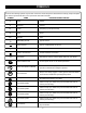
SYMBOLS Some of the following symbols may be used on this tool. Please study them and learn their meaning. Proper interpretation of these symbols will allow you to operate the tool better and safer.
SYMBOLS The following signal words and meanings are intended to explain the levels of risk associated with this product. SYMBOL SIGNAL MEANING DANGER: Indicates an imminently hazardous situation, which, if not avoided, will result in death or serious injury. WARNING: Indicates a potentially hazardous situation, which, if not avoided, could result in Death or serious injury. CAUTION: Indicates a potentially hazardous situation, which, if not avoided, may result in minor or moderate injury.
ELECTRICAL DOUBLE INSULATION EXTENSION CORDS Double insulation is a concept in safety in electric power tools, which eliminates the need for the usual threewire grounded power cord. All exposed metal parts are isolated from the internal metal motor components with protecting insulation. Double insulated tools do not need to be grounded. When using a power tool at a considerable distance from a power source, be sure to use an extension cord that has the capacity to handle the current the tool will draw.
FEATURES PRODUCT SPECIFICATIONS n Blade Diameter ................................. 7-1/4 in. (184 mm) n Input............................ 120 V, 60 Hz, AC Only, 14 Amps n Blade Arbor.............................................5/8 in. (16 mm) n No Load Speed..............................................5500 /min. n Cutting Depth at 0°............................. 2-3/8 in. (60 mm) n Net Weight .............................................. 12 lbs. (5.4 kg) n Cutting Depth at 45°.......................
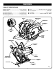
FEATURES KNOW YOUR LASER CIRCULAR SAW SPINDLE LOCK See Figure 1. The spindle lock allows you to secure the blade when turning the blade screw. Before attempting to use this product, familiarize yourself with all operating Features and Safety Rules NOTE: Do not run circular saw with spindle lock engaged. EDGE GUIDE DUST CHUTE Edge guide is used when making long or wide rip cuts with the saw.
ASSEMBLY ATTACHING BLADE n Depress spindle lock button. n Remove blade screw by turning it counterclockwise with the wrench. n Remove spring washer and outer blade washer ("D" washer). n Lift lower blade guard. n Remove blade. See Figures 2 - 3. Follow these directions to attach the blade. n Unplug the saw. CAUTION: To prevent damage to the spindle or spindle lock, always allow motor to come to a complete stop before engaging spindle lock. SPINDLE n Depress spindle lock button.
ASSEMBLY WARNING:: Current attachments and accessories available for use with this tool are listed above. Do not use any attachments or accessories not recommended by the manufacturer of this tool. The use of attachments or accessories not recommended can result in serious personal injury. EDGE GUIDE Use the edge guide provided when making long or wide rip cuts with the saw. TO ASSEMBLE EDGE GUIDE See Figure 5. Follow these directions to assemble the edge guide. n Unplug the saw.
OPERATION WARNING: Do not allow familiarity with tools to make you careless. Remember that a careless fraction of a second is sufficient to inflict serious injury. WARNING: Always wear safety goggles or safety glasses with side shields when operating power tools. Failure to do so could result in objects being thrown into your eyes resulting in possible serious injury. KICKBACK - BLADE SET TOO DEEP Fig.
OPERATION n Make straight cuts. Always use a straight edge guide when rip cutting. This helps prevent twisting the blade. n Use clean, sharp, and properly set blades. Never make cuts with dull blades. n Support the workpiece properly before beginning a cut. n Use steady, even pressure when making a cut. Never force a cut. n Do not cut warped or wet lumber. n Hold the saw firmly with both hands and keep your body in a balanced position so as to resist the forces if kickback should occur.
OPERATION USING THE LASER GUIDE n Locate depth of cut scale on back of upper blade guard. n Hold base flat against the workpiece and raise or lower saw until the indicator mark on bracket aligns with notch on blade guard. n Tighten depth adjustment knob securely. See Figure 13. WARNING: Do not stare into the laser beam or turn the laser on when the tool is not in use. Failure to do so could result in possible serious personal injury.The laser unit comes from the factory already installed and aligned.
OPERATION OPERATING THE SAW See Figures 15 - 17. It is important to understand the correct method for operating the saw. Refer to the figures in this section to learn the correct and incorrect ways for handling the saw. WARNING: To make sawing easier and safer, always maintain proper control of the saw. Loss of control could cause an accident resulting in possible serious injury.
OPERATION CROSS CUTTING/RIP CUTTING TOP VIEW OF SAW See Figure 18. When making a cross cut or rip cut, align the line of cut with the outer blade guide notch on the base as shown in the figure. Since blade thicknesses vary, always make a trial cut in scrap material along a guideline to determine how much, if any, you must offset the guideline to produce an accurate cut. BLADE GUIDE NOTCH NOTE: The distance from the line of cut to the guideline is the amount you should offset the guide.
OPERATION BEVEL CUTTING MOTOR HOUSING See Figures 20 - 21. To make the best possible cut, follow these helpful hints. n Align the line of cut with the inner blade guide notch on the base when making 45° bevel cuts. n Make a trial cut in scrap material along a guideline to determine how much you should offset the guideline on the cutting material. n Adjust the angle of the cut to any desired setting between zero and 51.5°. Refer to “TO ADJUST BEVEL SETTING” next.
OPERATION POSITIVE 0° BEVEL STOP See Figure 22. The saw has a positive 0° bevel stop that has been factory adjusted to assure 0° angle of the saw blade when making 90° cuts. TO CHECK POSITIVE 0° BEVEL STOP Follow these directions to check the positive 0° bevel stop. n Unplug your circular saw. �� �� �� �� BEVEL ADJUSTMENT KNOB WARNING: CARPENTER’S SQUARE Failure to unplug the tool could result in accidental starting causing serious injury. n Place the saw in an upside down position on a workbench.
OPERATION POCKET CUTTING n Release the trigger and allow the blade to come to a complete stop. n Lift the saw from the workpiece. n Clear corners out with a hand saw or sabre saw. See Figure 24. WARNING: Always adjust bevel setting to zero before making a pocket cut. Attempting a pocket cut at any other setting can result in loss of control of the saw possibly causing serious injury. WARNING: Never tie the lower blade guard in a raised position. Leaving the blade exposed could lead to serious injury.
MAINTENANCE REPLACING LASER GUIDE BATTERIES WARNING: See Figure 26. �n Unplug the saw. When servicing use only identical Ryobi replacement parts. Use of any other parts may create a hazard or cause product damage. �n Make sure laser is turned off. n Remove the laser cover by lifting it off its base. �n Remove both AAA batteries. WARNING: �n Install the two AAA batteries aligning the positives (+) with positives (+) and the negatives (-) with negatives (-) as shown on the inside base of laser.
NOTES 22
NOTES 23
OPERATOR'S MANUAL 7-1/4 in. LASER CIRCULAR SAW DOUBLE INSULATED CSB140LZ • SERVICE Now that you have purchased your tool, should a need ever exist for repair parts or service, simply contact your nearest Ryobi Authorized Service Center. Be sure to provide all pertinent facts when you call or visit. Please call 1-800-525-2579 for your nearest Ryobi Authorized Service Center. You can also check our web site at www.ryobitools.com for a complete list of Authorized Service Centers. • MODEL NO. AND SERIAL NO.