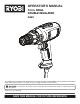
OPERATOR’S MANUAL 3/8 in. DRILL DOUBLE INSULATED D46C Your drill has been engineered and manufactured to our high standard for dependability, ease of operation, and operator safety. When properly cared for, it will give you years of rugged, trouble-free performance. WARNING: To reduce the risk of injury, the user must read and understand the operator's manual before using this product. Thank you for your purchase.
TABLE OF CONTENTS Introduction ...................................................................................................................................................................... 2 � General Safety Rules .....................................................................................................................................................3-4 � Specific Safety Rules ............................................................................................................
GENERAL SAFETY RULES Keep your work area clean and well lit. Cluttered benches and dark areas invite accidents. Do not operate power tools in explosive atmospheres, such as in the presence of flammable liquids, gases, or dust. Power tools create sparks which may ignite the dust or fumes. Keep bystanders, children, and visitors away while operating a power tool. Distractions can cause you to lose control. Avoid accidental starting. Be sure switch is off before plugging in.
GENERAL SAFETY RULES SERVICE When servicing a tool, use only identical replacement parts. Follow instructions in the Maintenance section of this manual. Use of unauthorized parts or failure to follow Maintenance Instructions may create a risk of shock or injury. Tool service must be performed only by qualified repair personnel. Service or maintenance performed by unqualified personnel may result in a risk of injury.
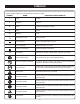
SYMBOLS Some of the following symbols may be used on this tool. Please study them and learn their meaning. Proper interpretation of these symbols will allow you to operate the tool better and safer.
SYMBOLS The following signal words and meanings are intended to explain the levels of risk associated with this product. SYMBOL SIGNAL MEANING DANGER: Indicates an imminently hazardous situation, which, if not avoided, will result in death or serious injury. WARNING: Indicates a potentially hazardous situation, which, if not avoided, could result in death or serious injury. CAUTION Indicates a potentially hazardous situation, which, if not avoided, may result in minor or moderate injury.
ELECTRICAL DOUBLE INSULATION EXTENSION CORDS Double insulation is a concept in safety in electric power tools, which eliminates the need for the usual threewire grounded power cord. All exposed metal parts are isolated from the internal metal motor components with protecting insulation. Double insulated tools do not need to be grounded. When using a power tool at a considerable distance from a power source, be sure to use an extension cord that has the capacity to handle the current the tool will draw.
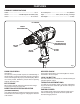
FEATURES PRODUCT SPECIFICATIONS Chuck ....................................................................... 3/8 in. No Load Speed ..............................................0-1,000/min. Switch............................. Variable Speed Reversible (VSR) Input ............................... 120 V, 60 Hz, AC only, 4.5 Amps Clutch ............................................................. 24 Positions Net Weight.............................................................. 3.8 lbs.
ASSEMBLY UNPACKING WARNING: This product has been shipped completely assembled. If any parts are damaged or missing do not operate this tool until the parts are replaced. Failure to heed this warning could result in serious personal injury. Carefully remove the tool and any accessories from the box. Make sure that all items listed in the packing list are included. Inspect the tool carefully to make sure no breakage or damage occurred during shipping.
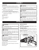
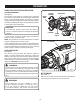
OPERATION DIRECTION OF ROTATION SELECTOR (FORWARD/REVERSE) See Figure 2. UNLOCK (RELEASE) The direction of bit rotation is reversible and is controlled by a selector located above the switch trigger. With the drill held in normal operating position, the direction of rotation selector should be positioned to the left of the switch trigger for drilling. The drilling direction is reversed when the selector is to the right of the switch trigger.
OPERATION INSTALLING BITS See Figure 5 - 6. Unplug the drill. CHUCK JAWS UNLOCK (RELEASE) CHUCK BODY Open or close the chuck jaws to a point where the opening is slightly larger than the bit size you intend to use. Also, raise the front of the drill slightly to keep the bit from falling out of the chuck jaws. Insert the drill bit. WARNING: DRILL BIT Make sure to insert the drill bit straight into the chuck jaws.
OPERATION ADJUSTABLE TORQUE CLUTCH TO DECREASE TORQUE See Figure 8. This product is equipped with an adjustable torque clutch for driving different types of screws into different materials. The proper setting depends on the type of material and the size of screw you are using. TORQUE ADJUSTMENT RING ADJUSTING TORQUE See Figure 8. There are twenty-four torque indicator settings located on the front of the drill. Rotate the adjusting ring to the desired setting.
MAINTENANCE WARNING: WARNING: Do not at any time let brake fluids, gasoline, petroleumbased products, penetrating oils, etc., come in contact with plastic parts. Chemicals can damage, weaken or destroy plastic which may result in serious personal injury. When servicing, use only identical replacement parts. Use of any other parts may create a hazard or cause product damage.
MAINTENANCE CHUCK REMOVAL MALLET See Figures 10 - 12. The chuck may be removed and replaced with a new one. Unplug the drill. CHUCK JAWS Insert a 5/16 in. or larger hex key into the chuck of the drill and tighten the chuck jaws securely. Tap the hex key sharply with a mallet in a clockwise direction. This will loosen the screw in the chuck for easy removal. Open the chuck jaws and remove the hex key. Using a screwdriver, remove the chuck screw by turning it in a clockwise direction.
NOTES 15
OPERATOR’S MANUAL 3/8 in. DRILL DOUBLE INSULATED D46C • SERVICE Now that you have purchased your tool, should a need ever exist for repair parts or service, simply contact your nearest Authorized Service Center. Be sure to provide all pertinent facts when you call or visit. Please call 1-800-525-2579 for your nearest Authorized Service Center. You can also check our web site at www.ryobitools.com for a complete list of Authorized Service Centers. • MODEL NO. AND SERIAL NO.