OWNER'S OPERATING MANUAL PLATE JOINER / JM80 DOUBLE INSULATED SPECIFICATIONS: No Load Speed Rating 10,000 rpm 120 volts, 60 Hz, AC 6.0 Amperes Fence Angle Adjustment With 45° Positive Stops 0 - 135° Fence Height Adjustment 0 - 2 In. Depth Of Cut With Micro Depth Of Cut Adjustment Net Weight 0 - 5/8 In. (16mm) 6.8 lbs THANK YOU FOR BUYING A RYOBI PLATE JOINER.
Table of Contents 1. 2. 3. 4. 5. 6. 7. 8. 9. Table of Contents / Introduction ............................................................... 2 Rules For Safe Operation ..................................................................... 4-6 Features ................................................................................................ 7-8 Adjustments .........................................................................................9-10 Operation ..........................................
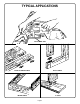
TYPICAL APPLICATIONS PLATE JOINER / JM80 EDGE-TO-EDGE JOINTS BUTT JOINTS MITER JOINTS T- JOINT Page 3
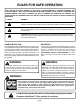
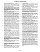
RULES FOR SAFE OPERATION THE PURPOSE OF SAFETY SYMBOLS IS TO ATTRACT YOUR ATTENTION TO POSSIBLE DANGERS. THE SAFETY SYMBOLS, AND THE EXPLANATIONS WITH THEM, DESERVE YOUR CAREFUL ATTENTION AND UNDERSTANDING. THE SAFETY WARNINGS DO NOT BY THEMSELVES ELIMINATE ANY DANGER. THE INSTRUCTIONS OR WARNINGS THEY GIVE ARE NOT SUBSTITUTES FOR PROPER ACCIDENT PREVENTION MEASURES. SYMBOL MEANING SAFETY ALERT SYMBOL: Indicates caution or warning. May be used in conjunction with other symbols or pictographs.
READ ALL INSTRUCTIONS 1. KNOW YOUR POWER TOOL - Read owner's manual carefully. Learn its applications and limitations as well as the specific potential hazards related to this tool. 2. GUARD AGAINST ELECTRICAL SHOCK BY PREVENTING BODY CONTACT WITH GROUNDED SURFACES. For example: Pipes, radiators, ranges, refrigerator enclosures. 3. KEEP WORK AREA CLEAN. Cluttered areas and benches invite accidents. 4. AVOID DANGEROUS ENVIRONMENT. Don't use power tools in damp or wet locations or expose to rain.
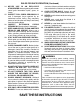
RULES FOR SAFE OPERATION (Continued) 24. NEVER USE IN AN EXPLOSIVE ATMOSPHERE. Normal sparking of the motor could ignite flammable liquids, gases, or fumes. 25. INSPECT TOOL CORDS PERIODICALLY and if damaged, have repaired by an authorized service facility. Stay constantly aware of cord location and keep it well away from the rotating blade. 26. INSPECT EXTENSION CORDS PERIODICALLY and replace if damaged. 27. KEEP HANDLES DRY, CLEAN, AND FREE FROM OIL AND GREASE. Always use a clean cloth when cleaning.
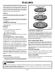
FEATURES Your Plate Joiner has been designed for making fast, accurate, and simple plunge cuts in wood, etc. so that biscuits can be used to join two or more boards together. When used properly and only for what it is intended, this versatile tool will give you years of trouble-free performance. It is professionally engineered, but its ease of operation allows the amateur to produce work that is beautiful and precise. #0 = 5/8 IN. X 1-13/16 IN. SWITCH #10 = 13/16 IN. X 2-1/16 IN.
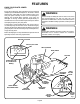
FEATURES KNOW YOUR PLATE JOINER See Figure 2. Except for the dust bag, your plate joiner has been shipped completely assembled and ready for use. An owner's manual and warranty registration are also included. Inspect your new plate joiner carefully to make sure no breakage or damage has occurred during shipping. If any parts are damaged or missing, contact your local Ryobi factory or authorized service center to obtain replacement parts before attempting to operate your plate joiner.
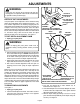
ADJUSTMENTS WARNING: If any parts are missing, do not operate tool until the missing parts are replaced. Failure to do so could result in possible serious personal injury. ROTATE TO DESIRED SETTING 0, 10, OR 20 DEPTH OF CUT ADJUSTMENTS Your plate joiner can be adjusted to three standard cutting depths to accommodate three standard size biscuits — #0, #10, and #20. Adjustments are made by engaging slots on depth adjustment knob with tabs on rear base assembly.
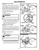
ADJUSTMENTS FENCE HEIGHT ADJUSTMENT See Figure 5. The adjustable fence on your plate joiner can be moved up and down to adjust the position of the blade in relation to the top of the workpiece. A scale on both sides of the fence indicates the height of the fence from the center of the blade. The fence can be positioned up to two inches from the center of the blade. However, the scale and indicator point can only be set up to 1-1/2 in. from the center of the blade. Scale marks are in increments of 1/16 in.
OPERATION WARNING: Always wear safety goggles or safety glasses with side shields when operating tools. Failure to do so could result in objects being thrown into your eyes, resulting in possible serious injury. INDICATOR MARK(S) A variety of spline joints can be made using your plate joiner. The number and size biscuits needed for each joint depends on the thickness of the wood and the length of the joint. In general, the small #0 biscuits should be used for miter cuts in 3/4 in. materials.
OPERATION BUTT JOINTS See Figure 9. A butt joint is one of the weakest joints in woodworking. This type of joint is mating the end grain of one board with the edge grain of another. The bonding of glue on this type of surface is poor. However, by using biscuits you can create a very strong joint that gives a mortise-and-tenon effect. BISCUIT SLOT(S) BISCUIT(S) HOW TO MAKE BUTT JOINTS 1. Unplug your plate joiner. 2. Place the two pieces of wood to be joined on a level workbench.
OPERATION T- JOINTS See Figures 11-15. A T-joint is used when the end of a board is joined to the face of another board as shown in figure 11. Attaching shelves to bookcases and inner support braces to frames are typical applications. Actual cutting of a T-joint is as simple as any other cut. However, it is critical that you mark the centerlines, mark the intersection points for each slot, and cut each slot correctly. See Figure 11. CENTERLINE MARK(S) BISCUIT(S) HOW TO MAKE T- JOINTS 1.
OPERATION T-JOINTS (Continued) 14. Repeat this procedure for cutting all required slots in vertical boards. 15. Once all slots have been cut, place a biscuit in each joint and dry assemble the workpieces. Make sure each joint lines up and fits. 16. Finally, disassemble the workpieces and place a bead of glue in each slot. Also, spread a bead of glue over the entire surface of the joint. Reinsert the biscuits and assemble the workpieces. See Figure 11. 17. Clamp workpieces together until the glue sets up.
OPERATION HOW TO MAKE EDGE MITER JOINTS 1. Unplug your plate joiner. 2. Place the pieces of wood to be joined on a level workbench as shown in figure 17. 3. Mark centerline of the joint on each board. 4. When making edge miter joints with workpieces that have different thicknesses, clamp securely to a workbench with the long sides up. This will assure that the outside surfaces will match. See Figure 18. 5. Loosen height adjusting knobs and set fence angle at 135°. 6.
OPERATION DUSTLESS FEATURE See Figure 20. The dust bag located on the rear of your plate joiner provides a dust collection system. Wood particles are drawn up through a tunnel in the base and collect in the dust bag during cutting operations. For more efficient operation, empty dust bag when half full. Do not connect plate joiner to power supply before installing dust bag.
MAINTENANCE ADJUSTABLE FENCE WARNING: TO REMOVE FRONT BASE ASSEMBLY When servicing, use only identical Ryobi replacement parts. Use of any other part may create a hazard or cause product damage. CLEANING BASE ASSEMBLY / DUST BAG TUNNEL See Figures 21-23. After extended use, wood particles and resin may build up inside the base assembly of your plate joiner and clog the path for wood particles going into dust bag.
MAINTENANCE BLADE REPLACEMENT See Figures 24-27. After extended use, the blade on your plate joiner may become dull and need replacing. If you accidentally hit a nail or other blunt object, it will break the carbide tips on the blade. These situations also require replacing the blade. ADJUSTABLE FENCE TO REMOVE FRONT BASE ASSEMBLY HOW TO REPLACE THE BLADE 1. Unplug your plate joiner.
MAINTENANCE HOW TO REPLACE THE BLADE (Continued) 16. 17. 18. 19. 20. 21. TO REMOVE NOTE: Saw teeth point toward the right of the saw when held in normal operating position. The direction of rotation is marked on the saw blade. An arrow on the bottom of the front base assembly also indicates direction of rotation. See Figure 24. Tighten blade screw securely. NOTE: Turn blade screw clockwise to tighten. Replace rear base assembly. Position adjustment rod in its proper place as shown in figure 25.
TROUBLESHOOTING PROBLEM SOLUTION 1. Biscuits do not fit slots. Biscuits not fitting slots may also cause misalignment of boards being joined. A. Biscuit slots are too deep or too shallow. Make fine adjustments to depth setting. See "TO MAKE FINE ADJUSTMENTS" section on page 9. B. Biscuit thickness may be out of tolerance. Compress biscuits in a vise if they are too thick. C. Check to see if biscuits are the correct size for the size slots that have been cut: #0, #10, or #20. D.
NOTES Page 21
OWNER'S OPERATING MANUAL PLATE JOINER / JM80 DOUBLE INSULATED EXTENSION CORD CAUTION When using a power tool at a considerable distance from a power source, be sure to use an extension cord that has the capacity to handle the current the tool will draw. An undersized cord will cause a drop in line voltage, resulting in overheating and loss of power. Use the chart to determine the minimum wire size required in an extension cord. Only round jacketed cords should be used.