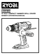
LCDI1802 18 VOLT COMPACT HAMMER DRILL DRIVER OWNER’S OPERATING MANUAL
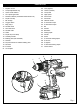
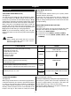
DESCRIPTION 1. 2. 3. 4. 5. 6. 7. 8. 9. 10. 11. 12. 13. 14. 15. 16. 17. 18. 19. 20. 21. 22. 23. 24. 25. 26. 27. 28. 29. 30. 31. 32. 33. 34. 35. 36. 37. 38. 39. 40. 41.
13 19 20 6 10 8 12 5 Fig. 4 11 14 41 15 22 Fig. 2 21 23 Fig. 5 31 32 33 4 9 7 17 24 25 16 LO HI 18 Fig. 3 Fig.
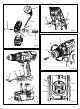
26 27 28 6 36 3 13 35 34 28 26 27 6 I Fig. 7 2 29 38 30 Fig. 8 41 22 40 21 37 39 35 23 Fig. 9 Fig.
Important! It is essential that you read the instructions in this manual before operating this machine. Subject to technical modifications.
English General Power Tool Safety Warnings protected supply. Use of an RCD reduces the risk of electric shock. NOTE: The term ''residual current device (RCD)'' may be replaced by the term ''ground fault circuit interrupter (GFCI)'' or ''earth leakage circuit breaker (ELCB)''. WARNING Read all safety warnings and all instructions. Failure to follow the warnings and instructions may result in electric shock, fire and/or serious injury.
English General Power Tool Safety Warnings knowledge, unless they have been given supervision or instruction concerning use of the appliance by a person responsible for their safety. Children should be supervised to ensure that they do not play with the appliance. Disconnect the plug from the power source and/ or the battery pack from the power tool before making any adjustments, changing accessories, or storing power tools.
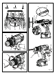
English ASSEMBLY WARNING Always wear safety goggles or safety glasses with side shields when operating products. Failure to do so could result in objects being thrown into your eyes, resulting in possible serious injury. Slide depth guide clamp into notch in collar. Clamp holds depth rod firmly in place. NOTE: When properly installed, the teeth on the depth stop rod should be aligned with the teeth indicator on the depth stop rod clamp. Thread auxiliary handle onto screw and secure tightly.
English OPERATION held in normal operating position, the rotation selector should be positioned to the left of the trigger switch for forward drilling. The drilling direction is reversed when the selector is to the right of the trigger switch. Place the battery pack on the tool. Make sure the latches on each side of the battery pack snap into place and the battery pack is secured on the tool before beginning operation.
English OPERATION QUICK MODE SELECTOR See Figure 7. The Quick Mode Selector allows you to quickly switch from drill mode to drive mode. In general, drill mode should be used for drilling and other heavy duty applications. Drive mode should be used for driving screws.percussion mode should be used for impact drilling. TWO-SPEED GEAR TRAIN (HI-LO) See Figure 6. The drill has a two-speed gear train designed for drilling or driving at LO (1) or HI (2) speeds.
English OPERATION INSTALLING BITS See Figure 9. Lock the trigger switch by placing the rotation selector in the center position. Open or close the chuck jaws to a point where the opening is slightly larger than the bit size you intend to use. Also, raise the front of the drill slightly to keep the bit from falling out of the chuck jaws. Insert the drill bit. Tighten the chuck jaws on the drill bit. BIT STORAGE See Figure 3.
English OPERATION WARNING Do not attempt to modify this tool or create accessories not recommended for use with this tool. Any such alteration or modification is misuse and could result in a hazardous condition leading to possible serious personal injury. WARNING: Be prepared for binding at bit breakthrough. When these situations occur, drill has a tendency to grab and kick opposite to the direction of rotation and could cause loss of control when breaking through material.
961067429-01