OPERATOR’S MANUAL Trimmer / Brushcutter PBC3046E RY70105A Your new trimmer has been engineered and manufactured to Ryobi’s high standard for dependability, ease of operation and operator safety. Properly cared for, it will give you years of rugged, trouble-free performance. WARNING: To reduce the risk of injury, the user must read and understand the operator’s manual. Thank you for buying a Ryobi trimmer.
TABLE OF CONTENTS ■ Safety ..................................................................................................................................................................... 2 - 3 ■ Symbols ................................................................................................................................................................. 4 - 5 ■ Technical Data .................................................................................................................
SAFETY ■ Inspect the unit before each use for loose fasteners, fuel leaks etc. Replace any damaged parts before use. ■ The string head or blade will rotate during carburettor adjustments. ■ It has been reported that vibrations from hand-held tools may contribute to a condition called Raynaud’s Syndrome in certain individuals. Symptoms may include tingling, numbness and blanching of the fingers, usually apparent upon exposure to cold.
SYMBOLS Important: Some of the following symbols may be used on your tool. Please study them and learn their meaning. Proper interpretation of these symbols will allow you to operate the tool better and more safely. SYMBOL NAME EXPLANATION Safety Alert Symbol Indicates danger, warning or caution. It means attention!!! Your safety is involved. Read Your Operator’s Manual Your manual contains special messages to bring attention to potential safety concerns as well as operating and servicing information.
SYMBOLS SYMBOL NAME EXPLANATION Switch On/Off Switch I = ON to Run O = OFF to Stop The purpose of safety symbols is to attract your attention to possible dangers. The safety symbols and the explanations with them deserve your careful attention and understanding. The safety warnings do not by themselves eliminate any danger. The instructions or warnings they give are not substitutes for proper accident prevention measures.
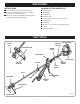
UNPACKING INSTRUCTIONS PACKING LIST FOR OWNER’S KIT ■ Carefully remove the product from the carton. ■ Inspect the product to make sure no breakage or damage occurred during carriage. ■ Do not discard the packing material until you have inspected and operated the product.
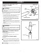
ASSEMBLY ATTACHING THE POWER HEAD TO THE TRIMMER ATTACHMENT TRIMMER SHAFT See Figure 2. COUPLER WARNING: GUIDE RECESS Never attach or adjust any attachment while power head is running. Failure to stop the engine can cause serious personal injury. The trimmer attachment connects to the power head by means of a coupler device. 1. Loosen the knob on the coupler of the power head shaft and remove the end cap from the attachment. 2. Push in the button located on the trimmer attachment shaft.
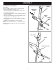
ASSEMBLY ATTACHING THE HANDLE SPACER See Figure 4. A barrier handle should be used for ensuring the best control and maximising operator safety. 1. Place the handle base and the bracket on the shaft housing below the spacer. 2. Install the two handle base screws and nuts, but do not tighten completely. 3. Place the front handle grip onto the handle base and install the two screws. Tighten securely. 4. Adjust the position of the front handle for best balance and comfort. 5.
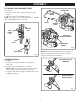
ASSEMBLY ATTACHING THE SHOULDER STRAP REAR HOUSING See Figure 5. 1. Connect the latch on the shoulder strap to the strap hanger. 2. Adjust the strap to a comfortable position. NOTE: To quickly release the product from the shoulder strap, sharply pull the quick release tab. TORQUE WRENCH SCREWS SILENCER GUARD SHOULDER STRAP QUICK RELEASE TAB BENT END OF SILENCER GUARD LATCH OPENING IN REAR HOUSING Fig.
ASSEMBLY BLADE GUARD FOUR SCREWS See Figure 8. 1. Attach the blade guard to the mounting bracket; install the four screws (10-24 x 3/4 in) from the top of the mounting bracket through the blade guard and into the threaded mounting plates. 2. Using the torque wrench supplied, tighten all four screws securely. NOTE: When using the string head, the string shield must be attached to blade guard. MOUNTING CLAMP BLADE GUARD NOTCHES GRASS DEFLECTOR See Figure 8. 1.
ASSEMBLY INSTALLING THE BLADE See Figure 10. 1. Place the upper flange washer over the gear shaft with the hollow side towards the blade guard. 2. Centre the blade on the upper flange, making sure the blade sits flat. Install the cupped washer with the raised centre away from the blade. Install the blade nut. The blade turns anticlockwise from the operator’s position. 3. Place the holding pin through the slot in the upper flange washer and the hole in the gear head.
OPERATION FUEL AND REFUELLING WARNING HANDLING THE FUEL SAFELY ■ Always handle fuel with care. It is highly flammable. ■ Always refuel outdoors where there are no sparks and flames. Do not inhale fuel vapour. ■ Do not let petrol or oil come in contact with your skin. ■ Keep petrol and oil away from the eyes. If petrol or oil comes in contact with the eyes, wash them immediately with clean water. If irritation is still present, see a doctor immediately. ■ Clean up spilled fuel immediately.
OPERATION ADVANCING THE STRING GRASS DEFLECTOR LINE TRIMMING CUTOFF BLADE ADVANCING STRING USING THE EZ LINE™ TAP ADVANCE SYSTEM String advance is controlled by tapping string head on grass while running engine at full throttle. 1. Run engine at full throttle. 2. Tap string head on ground to advance string. String advances each time the head is tapped. 3. Several taps may be required until string strikes the cutoff blade. 4. Resume trimming.
OPERATION OPERATING THE BRUSHCUTTER Hold the brushcutter with the right hand on the rear handle and the left hand on the front handle. Keep a firm grip with both hands while in operation. Brushcutter should be held at a comfortable position with the trigger handle about hip height. Maintain your grip and balance on both feet. Position yourself so that you will not be drawn off balance by the kick-back reaction of the cutting blade.
OPERATION STARTING AND STOPPING IGNITION SWITCH I = ON TO RUN O = OFF TO STOP See Figures 16 and 17. NOTE: The unit is equipped with an automatic choke feature. The starting instructions for this feature are different from units with a manual choke. Be sure to read and follow the starting instructions below. WARNING Never start or run the engine inside a closed or poorly ventilated area; breathing exhaust fumes can kill. THROTTLE INTERLOCK TO START A COLD ENGINE: 1 Lay trimmer on a flat, bare surface.
MAINTENANCE 6. Make sure the string head and the spool retainer are installed on the shaft by turning the retainer anticlockwise to tighten. 7. Pull the strings again to rotate the spool into cutting position. Push the spool retainer down while pulling on string(s) to manually advance the string and to check for proper assembly of the string head. WARNING: Use only original manufacturer’s replacement parts, accessories and attachments.
MAINTENANCE STRING REPLACEMENT See Figures 20 and 21. 1. Stop the engine, disconnect the sparking plug wire. Hold the string head and unscrew the spool retainer. Turn clockwise. 2. Remove the spool from the string head. NOTE: Keep the spring attached to the spool. Remove any old string remaining on the spool. 3. Cut two pieces of string, each being approximately 2.7 m (9 ft) long. 4. Insert the first string into the anchor hole in the upper part of the spool.
MAINTENANCE CLEANING THE EXHAUST PORT AND SILENCER LATCH Depending on the type of fuel used, the type and amount of oil used, and/or your operating conditions, the exhaust port and silencer may become blocked with carbon deposits. If you notice a power loss with your petrol-powered tool, a qualified service technician will need to remove these deposits to restore performance.
MAINTENANCE FUEL CAP STORAGE (1 MONTH OR LONGER) 1. Drain all fuel from tank into a container approved for petrol. Run engine until it stops. 2. Clean all foreign material from the trimmer. Store it in a well-ventilated place that is inaccessible to children. Keep away from corrosive agents such as garden chemicals and de-icing salts. 3. Cover the blade with the blade protector before storing the unit, or during transport. 4.
TROUBLESHOOTING IF THESE SOLUTIONS DO NOT SOLVE THE PROBLEM CONTACT YOUR AUTHORISED SERVICE DEALER. PROBLEM Engine will not start: POSSIBLE CAUSE SOLUTION 1. No spark. 2. No fuel. 3. Flooded engine. 4. Starter rope pulls harder now than when new. 1. Check spark. Remove sparking plug. Reattach the sparking plug cap and lay sparking plug on metal cylinder. Pull the starter rope and watch for spark at sparking plug tip. If there is no spark, repeat test with a new sparking plug. 2.
TROUBLESHOOTING IF THESE SOLUTIONS DO NOT SOLVE THE PROBLEM, CONTACT YOUR AUTHORISED SERVICE DEALER. PROBLEM POSSIBLE CAUSE SOLUTION String will not advance: 1. String welded to itself. 2. Not enough string on spool. 1. Lubricate with silicone spray. 2. Install more string. Refer to “String Replacement” earlier in this manual. 3. Pull strings while alternately pressing down on and releasing spool retainer. 4. Remove string from spool and rewind. Refer to “String Replacement” earlier in this manual. 5.
WARRANTY GUARANTEE – STATEMENT (RTSA / RTUK / RTG) All Ryobi products are guaranteed from defects in material and workmanship, for a period of twenty-four (24) months, effective and evidenced from date of original invoice or delivery note. Defects caused by normal wear and tear, unauthorised/improper maintenance/handling or overload are excluded from this guarantee, as are accessories such as battery packs, bulbs, blades and bits etc.
NOTES 23
OPERATOR’S MANUAL Trimmer / Brushcutter PBC3046E RY70105A Ryobi Technologies GmbH Itterpark 7 D-40724 Hilden Germany Tel.: +49 (0)2103 / 29 58 0 Fax : +49 (0)2103 / 29 58 29 info@ryobi-rtg.