OPERATOR'S MANUAL RE1802M ROUTER With R181FB Fixed Base, R181PF Plunge Base, and R181D D-Handle Base Double Insulated 1/ 3 2 01 3/ 2 15/32 7/16 13 / 32 Your new router has been engineered and manufactured to our Ryobi’s high standard for dependability, ease of operation, and operator safety. When properly cared for, the router will give you years of rugged, trouble-free performance.
TABLE OF CONTENTS ■ Introduction .................................................................................................................................................................... 2 ■ General Safety Rules .................................................................................................................................................. 3-4 ■ Specific Safety Rules .............................................................................................................
GENERAL SAFETY RULES ■ Remove adjusting keys or wrenches before turning the tool on. A wrench or a key that is left attached to a rotating part of the tool may result in personal injury. ■ Do not overreach. Keep proper footing and balance at all times. Proper footing and balance enables better control of the tool in unexpected situations. ■ Use safety equipment. Always wear eye protection. Dust mask, nonskid safety shoes, hard hat, or hearing protection must be used for appropriate conditions.
GENERAL SAFETY RULES ■ When servicing a tool, use only identical replacement parts. Follow instructions in the Maintenance section of this manual. Use of unauthorized parts or failure to follow Maintenance Instructions may create a risk of electric shock or injury. SERVICE ■ Tool service must be performed only by qualified repair personnel. Service or maintenance performed by unqualified personnel could result in a risk of injury.
SYMBOLS Important: Some of the following symbols may be used on this tool. Please study them and learn their meaning. Proper interpretation of these symbols will allow you to operate the tool better and safer.
ELECTRICAL DOUBLE INSULATION EXTENSION CORDS Double insulation is a concept in safety in electric power tools, which eliminates the need for the usual three-wire grounded power cord. All exposed metal parts are isolated from the internal metal motor components with protecting insulation. Double insulated tools do not need to be grounded. Important: Servicing of a tool with double insulation requires extreme care and knowledge of the system and should be performed only by a qualified service technician.
FEATURES SPECIFICATIONS Depth of Cut: Plunge Base ............................................................................................................................ 0 - 2 in. (0 - 51 mm) Fixed Base & D-Base ........................................................................................................ 0 - 1-1/2 in. (0 - 38 mm) Collet ........................................................................................................................................................
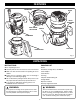
FEATURES LOCKING ARM SWITCH DEPTH ADJUSTMENT RING GOLD SPINDLE LOCK BUTTON HANDLE PLUNGE BASE 1/ 3 2 01 3/ 2 15/32 7/16 13 / 32 CHIP SHIELD D-HANDLE BASE 1/ 3 2 01 3/ 2 15/32 7/16 13 /32 Fig. 1 UNPACKING INSTRUCTIONS PACKING LIST When unpacking the tool: ■ Carefully remove the tool and accessories from the box. ■ Make sure that all items listed in the packing list are included. ■ Inspect the tool carefully to make sure no breakage or damage occurred during shipping.
OPERATION WARNING: Always wear safety goggles or safety glasses with side shields when using your router. Failure to do so could result in dust, shavings, chips, loose particles, or foreign objects being thrown in your eyes resulting in possible serious injury. If the operation is dusty, also wear a face or dust mask. ON OFF Fig. 2 TURNING THE ROUTER ON/OFF See Figure 2. ■ To turn on the router: Move the switch to the I position. ■ To turn off the router: Move the switch to the O position.
OPERATION WARNING: Never connect the router to power supply when you are assembling parts, making adjustments, installing or removing cutters, or when not in use. Disconnecting the router prevents accidental starting that could cause serious injury. REMOVING AND INSTALLING THE ROUTER BASE GOLD SPINDLE LOCK BUTTON TO SWITCH FROM THE FIXED BASE OR D-HANDLE BASE TO THE PLUNGE BASE See Figure 4. TO REMOVE THE FIXED OR D-HANDLE BASE: 1. Unplug the router.
OPERATION TO SWITCH FROM PLUNGE BASE TO FIXED BASE OR D-HANDLE BASE See Figures 6 and 7. LOCKING KNOB TO REMOVE THE PLUNGE BASE 1. Unplug the router. WARNING: Failure to unplug the tool could result in accidental starting causing serious injury. GOLD SPINDLE LOCK BUTTON 2. Place the router on a flat surface. 3. Loosen the locking knob. 4. Depress and hold the gold spindle lock button. The gold spindle lock button will not depress fully unless it is in line with the hole in the collet. 5.
OPERATION REMOVING/INSERTING CUTTERS See Figure 8. Follow these steps to remove or insert cutters. 1. Unplug the router. TO LOOSEN WARNING: Failure to unplug the tool could result in accidental starting causing serious injury. TO TIGHTEN CAUTION: To prevent damage to the spindle or spindle lock, always allow motor to come to a complete stop before engaging the spindle lock. 2. Depress the gold spindle lock button. 3. Place the router upside down on a workbench in order to gain easy access to collet nut.
OPERATION ADJUSTING DEPTH OF CUT Proper depth of cut depends on several factors: the peak horsepower of the router motor, the type of cutter, and the type of wood. A lightweight, low horsepower router is designed for making shallow cuts. A router with a high horsepower rating can safely cut deeper. Small cutters, such as veining bits with 1/16 in. (1.6 mm) cutting diameters, are designed to remove only small amounts of wood.
OPERATION TO ADJUST DEPTH OF CUT FOR PLUNGE BASE ROUTERS See Figures 11, 12, and 13. Follow these steps to adjust depth of cut for plunge base routers. 1. Unplug the router. PLUNGE LOCK LEVER WARNING: Failure to unplug the tool could result in serious injury due to accidental starting. 2. 3. 4. 5. 6. 7. 8. 9. 10. 11. 12. 13. 14. 15. 16. Place the router on a flat surface. Loosen the stop bar knob. Unlock the plunge lock lever. Plunge the router until the tip of the cutter touches the flat surface.
OPERATION FEEDING THE ROUTER 6 The “secret” of professional routing and edge shaping lies in making a careful set-up for the cut and in selecting the proper rate of feed. 5 3 DIRECTION (EXTERNAL) See Figures 14 and 15. When routing, the cutter rotates clockwise. Therefore, you should feed the router into the workpiece from left to right. When you feed the router from left to right, the rotation of the cutter pulls the router against the workpiece.
OPERATION RATE OF FEED The proper rate of feed depends on several factors: the hardness and moisture content of the wood, the depth of cut, and the cutting diameter of the bit. When cutting shallow grooves in soft woods such as pine, a faster rate of feed can be used. When making deep cuts in hardwoods such as oak, a slower rate of feed should be used. The best rate of feed is one that does not slow down the router motor more than one-third of its no-load speed.
OPERATION DETERMINING DEPTH OF CUT See Figure 19. As previously mentioned, the depth of cut is important because it affects the rate of feed that, in turn, affects the quality of the cut (and, also, the possibility of damage to your router motor and bit). A deep cut requires a slower feed than a shallow one, and a too deep cut will cause you to slow the feed so much that the bit is no longer cutting, it is scraping, instead. Making a deep cut is never advisable.
OPERATION When routing a groove wider than the diameter of the cutter, clamp a straightedge on both sides of the cutlines. Position both guides parallel to the desired line of cut and spaced equal distances from the desired edges of the groove. Rout along one guide; then, reverse direction and rout along the other guide. Clean out any remaining waste in the center of the groove freehand. ROUTING BY FREEHAND See Figure 21. When used freehand, your router becomes a flexible and versatile tool.
OPERATION EDGING WITH PILOTS ROUTER See Figure 22. You can cut rabbets and molded edges using piloted cutters. The pilot, which extends below the cutter, allows the cutter to turn while the pilot follows the edge of the workpiece. Some pilots are solid extensions of the cutter. Others are ball bearing guides that are fastened to the end of the cutter. Arbor-type bits with pilots are excellent for quick, easy edge shaping. They follow workpiece edges that are either straight or curved.
OPERATION ROUTER TEMPLATE GUIDE BUSHING KIT ROUTER BIT Sizes: 5/16 in., 7/16 in. (Short), 7/16 in. (Long), 1/2 in., and 5/8 in. SCREW TEMPLATE GUIDE BUSHING SCREW ROUTING WITH THE GUIDE BUSHING ALIGN CUTOUTS WITH HOLES IN BASE You can accurately duplicate curves and complex shapes by fitting your router with a template guide bushing that extends below the subbase. The router bit passes through the guide bushing. The guide bushing then rides against a template.
OPERATION STRAIGHT GUIDE The straight guide is used as an edge guide that slides against the edge of a board to guide the cutter through the cut. The straight guide can be used from either side of the router base. TO INSTALL THE STRAIGHT GUIDE See Figures 25 and 26. ■ Unplug your router. SUBBASE 7 16 3 32 1 0 16 15 32 12 1 32 STRAIGHT GUIDE MOUNTING POSTS WARNING: Failure to unplug your router could result in accidental starting causing serious injury.
MAINTENANCE WARNING: When servicing use only identical Ryobi replacement parts. Use of any other parts may create a hazard or cause product damage. GENERAL LUBRICATION Avoid using solvents when cleaning plastic parts. Most plastics are susceptible to damage from various types of commercial solvents and may be damaged by their use. Use clean cloths to remove dirt, carbon dust, etc.
NOTES 23
OPERATOR'S MANUAL RE1802M ROUTER With R181FB Fixed Base, R181PF Plunge Base, and R181D D-Handle Base Double Insulated • SERVICE Now that you have purchased your tool, should a need ever exist for repair parts or service, simply contact your nearest Ryobi Authorized Service Center. Be sure to provide all pertinent facts when you call or visit. Please call 1-800-525-2579 for your nearest Ryobi Authorized Service Center. You can also check our Web site at www.ryobitools.