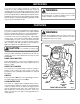
OPERATOR'S MANUAL ROUTER - RE170VS 3 16 1 32 11 64 DOUBLE INSULATED 1 64 0 15 64 7 32 13 64 SPECIFICATIONS: Depth Of Cut Collet Also Included With Packaging Amperes Peak Horsepower Rating No Load Speed Net Weight 0 - 1-1/2 in. (0 - 38.1 mm) 1/2 in. (13 mm) 1/4 in. (6.4 mm) 8.5 1-3/4 120 Volts, 60 Hz, AC Only 15,000 - 25,000 RPM 3.92 kg. (8.625 lbs.) THANK YOU FOR BUYING A RYOBI ROUTER.
TABLE OF CONTENTS ■ Product Specifications ..................................................................................................... 1 ■ Typical Applications ......................................................................................................... 2 ■ Rules For Safe Operation .............................................................................................3-5 ■ Unpacking ...........................................................................................
RULES FOR SAFE OPERATION The purpose of safety symbols is to attract your attention to possible dangers. The safety symbols, and the explanations with them, deserve your careful attention and understanding. The safety warnings do not by themselves eliminate any danger. The instructions or warnings they give are not substitutes for proper accident prevention measures. SYMBOL MEANING SAFETY ALERT SYMBOL: Indicates caution or warning. May be used in conjunction with other symbols or pictographs.
READ ALL INSTRUCTIONS 1. 2. KNOW YOUR POWER TOOL. Read operator's manual carefully. Learn its applications and limitations as well as the specific potential hazards related to this tool. GUARD AGAINST ELECTRICAL SHOCK by preventing body contact with grounded surfaces. For example: Pipes, radiators, ranges, refrigerator enclosures. 14. DON'T ABUSE CORD. Never carry tool by cord or yank it to disconnect from receptacle. Keep cord from heat, oil and sharp edges. 15. SECURE WORK.
RULES FOR SAFE OPERATION (Continued) 25. NEVER USE IN AN EXPLOSIVE ATMOSPHERE. Normal sparking of the motor could ignite fumes. 26. INSPECT TOOL CORDS PERIODICALLY and if damaged, have repaired at your nearest AUTHORIZED SERVICE CENTER. Stay constantly aware of cord location. 27. INSPECT EXTENSION CORDS PERIODICALLY and replace if damaged. 28. KEEP HANDLES DRY, CLEAN, AND FREE FROM OIL AND GREASE. Always use a clean cloth when cleaning.
UNPACKING Your router has been shipped completely assembled and ready for use. After removing it from the box, inspect it carefully to make sure no breakage or damage has occurred during shipping. If any parts are damaged or missing, contact your nearest Ryobi dealer to obtain replacement parts before attempting to operate router. A 1/4 in. (6.4 mm) collet assembly, wrench, operator's manual, and warranty registration are the only loose parts included in the box.
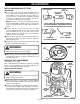
FEATURES CHIP SHIELD APPLICATIONS A clear plastic see-through chip shield is installed on the front of your router for protection against flying dust and chips. The shield is designed to fit the front opening of the router base. See Figure 1. If necessary to remove chip shield, squeeze the tabs on each end and pull outward. To replace, squeeze the tabs at each end, fit into opening, then release. FOR YOUR PROTECTION, DO NOT USE ROUTER WITHOUT CHIP SHIELD PROPERLY IN PLACE.
ADJUSTMENTS SPINDLE LOCK WARNING: Your router should never be connected to power supply when you are assembling parts, making adjustments, installing or removing cutters, or when not in use. Disconnecting your router will prevent accidental starting that could cause serious injury. 1 INSTALLING/REMOVING CUTTERS 1 3 See Figures 3, 4, and 5. 3 2 2 ■ UNPLUG YOUR ROUTER.
ADJUSTMENTS INSTALLING/REMOVING CUTTERS (Continued) 1/2 IN. COLLET NUT MOTOR SHAFT ■ To use cutters with 1/4 in. (6.4 mm) shank bits, the 1/2 in. (13 mm) collet assembly must be removed and replaced with the 1/4 in. (6.4 mm) collet assembly. Remove the 1/2 in. (13 mm) collet assembly by removing collet nut, loosening collet screw securing collet to motor shaft, then removing collet assembly. NOTE: The collet screw has left hand threads and you will need a #2 phillips screwdriver to loosen collet screw.
ADJUSTMENTS 3 16 1 32 ■ Position your router so that the cutter can extend below the subbase for desired depth setting. See Figure 8. ■ Turn the depth adjusting ring to obtain the desired depth of cut. The distance the cutter moves can be read on the depth adjusting ring. Each mark on the depth adjusting ring indicates 1/64 inch (.4 mm) change in depth setting. One indicator point is located on front of the motor housing, the other one is located on the base.
OPERATION ■ Make sure there is not a cutter in the collet. ■ Make sure the collet does not extend below the subbase. ■ Choose the desired speed from the speed selection chart. See Figure 10. ■ Turn the variable speed control selector to the desired setting. Align desired setting on the variable speed control selector with indicator mark on the lower end cap. ■ Plug your router into power supply source. ■ Grasp your router firmly with both hands and turn on.
OPERATION PROPER FEEDING The right feed is neither too fast nor too slow. It is the rate at which the bit is being advanced firmly and surely to produce a continuous spiral of uniform chips — without hogging into the wood to make large individual chips or, on the other hand, to create only sawdust. If you are making a small diameter, shallow groove in soft, dry wood, the proper feed may be about as fast as you can travel your router along your guide line.
OPERATION DEPTH OF CUT As previously mentioned, the depth of cut is important because it affects the rate of feed which, in turn, affects the quality of a cut (and, also, the possibility of damage to your router motor and bit). A deep cut requires a slower feed than a shallow one, and a too deep cut will cause you to slow the feed so much that the bit is no longer cutting, it is scraping, instead . Making a deep cut is never advisable. The smaller bits — especially those only 1/16 inch (1.
OPERATION STARTING AND ENDING A CUT INTERNAL ROUTING ROUTER Tilt router and place on workpiece, letting edge of subbase contact workpiece first. Be careful not to let router bit contact workpiece. Turn router on and let motor build to its full speed. Gradually feed cutter into workpiece until subbase is level with workpiece. PILOT WARNING: WORK Keep a firm grip on router with both hands at all times. Failure to do so could result in loss of control leading to possible serious injury.
OPERATION EDGE ROUTING Place router on workpiece, making sure the router bit does not contact workpiece. Turn router on and let motor build to its full speed. Begin your cut, gradually feeding cutter into workpiece. WARNING: 3 3 13 64 16 64 3 Keep a firm grip on router with both hands at all times. Failure to do so could result in loss of control leading to possible serious injury.
OPERATION FREEHAND ROUTING 3 1 64 0 When freehand routing, we suggest the following: ■ Draw or layout the pattern on workpiece. ■ Choose the appropriate cutter. NOTE: A core box or Vgroove bit is often used for routing letters and engraving objects. Straight bits and ball mills are often used to make relief carvings. Veining bits are used to carve small, intricate details. ■ Rout the pattern in two or more passes. Make the first pass at 25% of the desired depth of cut.
OPERATION #10-32 PAN HEAD SCREW 5/16-18 X 3/4 IN. FLATHEAD SCREW BASE BASE SUBBASE Fig. 23 Fig. 22 MAINTENANCE WARNING: When servicing use only identical Ryobi replacement parts. Use of any other parts may create a hazard or cause product damage. GENERAL Avoid using solvents when cleaning plastic parts. Most plastics are susceptible to damage from various types of commercial solvents and may be damaged by their use. Use clean cloths to remove dirt, carbon dust, etc.
OPTIONAL ACCESSORIES The following recommended accessories are current and were available at the time this manual was printed: ITEM NO. 4070175 4070176 6090080 DESCRIPTION Template Guide Adapter For Ryobi Template Guides Template Guide Adapter For Porter Cable Rockwell and B&D Template Guides Straight Guide For Ryobi Routers - Model Nos. R160, R165, RE 170, RE170VS, R175, RE175, R180, and RE185 HELPFUL HINTS ✓ ✓ ✓ ✓ ✓ ✓ ✓ ✓ ✓ ✓ ✓ ✓ Always clamp workpiece securely before routing.
NOTES Page 19
RYOBI ROUTER – MODEL NUMBER RE170VS 2 3 4 1 6 4 5 7 14 16 15 8 28 29 53 9 13 52 51 30 52 12 10 17 50 11 31 Page 20 31 18 15 34 35 32 19 33 33 22 48 49 58 57 59 46 42 26 26 47 55 56 50 41 15 27 39 40 23 25 24 49 38 21 20 36 37 54 44 43 25 43 61 45 63 62 61 61 62 63 60 64 WARNING: Improper repair of a double insulated tool can result in damages to the double insulation system possibly causing electrical shock or electrocution.
RYOBI ROUTER – MODEL NUMBER RE170VS The model number will be found on a plate attached to the motor housing. Always mention the model number in all correspondence regarding your ROUTER or when ordering repair parts. PARTS LIST Page 21 Key No.
RYOBI ROUTER – MODEL NUMBER RE170VS BLACK POWER CORD LEAD BLACK POWER HANDLE LEAD POWER CORD POWER HANDLE CORD SWITCH YELLOW BRUSH LEAD BROWN BLACK BLUE WHITE Page 22 SPEED CONTROL MODULE MOTOR YELLOW BRUSH LEAD BROWN BLACK SWITCH TRIGGER WIRING DIAGRAM
OPERATOR'S MANUAL ROUTER - RE170VS DOUBLE INSULATED EXTENSION CORD CAUTION When using a power tool at a considerable distance from a power source, be sure to use an extension cord that has the capacity to handle the current the tool will draw. An undersized cord will cause a drop in line voltage, resulting in overheating and loss of power. Use the chart to determine the minimum wire size required in an extension cord. Only round jacketed cords should be used.