
Use and Care Manual

10 — English
WARNING:
If any parts are damaged or missing do not operate this
product until the parts are replaced. Use of this product
with damaged or missing parts could result in serious
personal injury.
WARNING:
Do not attempt to modify this product or create acces-
sories not recommended for use with this product. Any
such alteration or modification is misuse and could result
in a hazardous condition leading to possible serious
personal injury.
WARNING:
Do not connect to power supply until assembly is com-
plete. Failure to comply could result in accidental starting
and possible serious personal injury.
TOOLS NEEDED
See Figure 4.
The following tool (not included or drawn to scale) is needed
for assembly:
Screwdriver
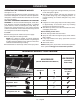
INSTALLING THE WHEELS
See Figure 5.
Locate the axles, hitch pins, washers, and wheels.
Slide the axle through the hole in the center of the wheel.
Slide a washer onto the axle before inserting into the
frame.
Lift the machine and slide the axle into the wheel mount-
ing hole in the machine base as shown.
Slide the washer on the axle, then push the hitch pin into
the hole on the end of the axle to secure the wheel as-
sembly.
NOTE: The hitch pin should be pushed into the axle until
the center of the pin rests on top of the axle.
Repeat with the second wheel.
INSTALLING THE HANDLE
See Figure 6.
Push and hold the push-pin button on the side of the handle
as you slide the handle onto the frame.
NOTE: Before use, pull the handle up until the lock button
snaps through the locking slots to secure the handle in place.
ATTACHING THE SPRAY WAND STORAGE
BRACKET
See Figure 7.
Place the spray wand storage bracket over the holes in
the frame.
Insert a screw through each of the holes and tighten
securely.
INSTALLING THE SPRAY WAND
See Figure 8.
Push the end of the spray wand into the trigger handle
and rotate clockwise to secure.
Place the assembled spray wand in the spray wand stor-
age bracket.
Pull on the spray wand to be certain it is properly secured.
CONNECTING HIGH PRESSURE HOSE TO
TRIGGER HANDLE
See Figure 9.
Screw the collar on the high pressure hose into the trigger
handle inlet coupler by turning the hose collar clockwise.
Tighten securely.
NOTE: Be careful to avoid cross-threading, which can
cause the trigger handle to leak during use.
Pull on the hose to be certain it is properly secured.
CONNECTING THE HIGH PRESSURE HOSE TO
THE PUMP
See Figure 10.
Completely uncoil and straighten the high pressure hose
to prevent kinks.
NOTE: See Using The High Pressure Hose in Operation
for more information about using the high pressure hose.
Align the collar on the threaded outlet on the pump.
Insert the hose on the end of the high pressure hose collar
into the threaded outlet.
Turn the collar clockwise to tighten the hose securely to
the pump.
NOTE: Be careful to avoid cross-threading, which can
cause the hose to leak during use.
Pull on the hose to be certain it is properly secured.
CONNECTING THE GARDEN HOSE
See Figure 11.
NOTICE:
Always observe all local regulations when connecting
hoses to the water main. Some areas have restrictions
against connecting directly to public drinking water sup-
ply to prevent the feedback of chemicals into the drinking
water supply. Direct connection through a receiver tank
or backflow preventer is usually permitted.
ASSEMBLY