OPERATOR’S MANUAL TP30 GAS PRUNER RY52014 Your pruner has been engineered and manufactured to our high standard for dependability, ease of operation, and operator safety. When properly cared for, it will give you years of rugged, trouble-free performance. WARNING: To reduce the risk of injury, the user must read and understand the operator’s manual before using this product. Thank you for your purchase.
TABLE OF CONTENTS Introduction ..................................................................................................................................................................... 2 � General Safety Rules ....................................................................................................................................................... 3 � Specific Safety Rules.............................................................................................................
GENERAL SAFETY RULES � Always stop the engine and remove the spark plug wire before making any adjustments or repairs except for carburetor adjustments. WARNING! Read and understand all instructions. Failure to follow all instructions listed below, may result in electric shock, fire and/or serious personal injury. � Inspect the unit before each use for loose fasteners, fuel leaks, etc. Replace any damaged parts before use. � The chain may rotate during carburetor adjustments.
SPECIFIC SAFETY RULES To protect yourself from falling branches, do not stand directly under the branch or limb being cut. This unit should not be held at an angle over 60° from ground level. Kickback is a dangerous reaction that can lead to serious injury. Kickback may occur when the moving chain contacts an object at the upper portion of the tip of the guide bar or when the wood closes in and pinches the chain in the cut.
SYMBOLS Some of the following symbols may be used on this tool. Please study them and learn their meaning. Proper interpretation of these symbols will allow you to operate the tool better and safer. SYMBOL NAME DESIGNATION/EXPLANATION Safety Alert Precautions that involve your safety. Read The Operator’s Manual To reduce the risk of injury, user must read and understand operator’s manual before using this product.
SYMBOLS The following signal words and meanings are intended to explain the levels of risk associated with this product. SYMBOL SIGNAL MEANING DANGER: Indicates an imminently hazardous situation, which, if not avoided, will result in death or serious injury. WARNING: Indicates a potentially hazardous situation, which, if not avoided, could result in death or serious injury. CAUTION: Indicates a potentially hazardous situation, which, if not avoided, may result in minor or moderate injury.
FEATURES PRODUCT SPECIFICATIONS Engine Displacement ......................................................................................................................................................30cc Bar length ....................................................................................................................................................................... 10 in. Weight ................................................................................................................
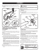
ASSEMBLY ATTACHING THE “J” BARRIER HANDLE UNPACKING See Figure 2. Hold the top and bottom clamp snugly in position on the shaft housing so that the handle will be located to the operator’s left. This product requires assembly. Carefully remove the tool and any accessories from the box. Make sure that all items listed in the packing list are included. Inspect the tool carefully to make sure no breakage or damage occurred during shipping.
ASSEMBLY Reinstall the bolt, lock washer, and hex nut to secure. WARNING: Connect the latch on the shoulder harness to the strap hanger. “J” BARRIER HANDLE Be certain the knob is fully tightened before operating equipment; check it periodically for tightness during use to avoid serious injury. SHOULDER STRAP To remove: Loosen the knob. LATCH Push in the button and twist the shafts to remove and separate ends.
ASSEMBLY NOTE: It is normal for smoke to be emitted from a new engine after first use. FILLING TANK Clean surface around fuel cap to prevent contamination. WARNING: Loosen fuel cap slowly. Rest the cap on a clean surface. Always shut off engine before fueling. Never add fuel to a machine with a running or hot engine. Move at least 30 ft. from refueling site before starting the engine. Do not smoke! Carefully pour fuel into the tank. Avoid spillage.
OPERATION N � OTE: For second and final cuts (from top of limb or branch), hold front cutting guide against the limb being cut. This will help steady the limb and make it easier to cut. Allow chain to cut for you; exert only light downward pressure. If you force the cut, damage to the bar, chain, or engine can result. Release the trigger as soon as the cut is completed, allowing the engine to idle.
OPERATION POSITION FOR STARTING PRIMER BULB See Figure 9. Lay the pruner on the ground and ensure that no objects or obstructions are in the immediate vicinity. Make sure nothing can come in contact with the bar and chain. STARTER GRIP ENGINE SWITCH STARTING INSTRUCTION LABEL Fig. 9 STARTING AND STOPPING See Figures 10 - 12. TO START A COLD ENGINE: DO NOT squeeze the throttle trigger until the engine starts and runs. � Lay the trimmer on a flat, bare surface. THROTTLE TRIGGER Fig.
MAINTENANCE Stop the engine before setting the chain tension. Make sure the guide bar nut is loose to finger tight, turn the chain tensioning screw clockwise to tension the chain. Refer to Replacing the Bar and Chain for additional information. WARNING: When servicing, use only identical replacement parts. Use of any other parts may create a hazard or cause product damage.
MAINTENANCE REPLACING THE BAR Remove all slack from chain by turning the chain tensioning screw clockwise, assuring that the chain seats into the bar groove during tensioning. See Figures 15 - 20. Lift the tip of the bar up to check for sag. Release the tip of the bar, and turn the chain tensioning screw 1/2 turn clockwise. Repeat this process until sag does not exist. WARNING: To avoid possible serious injury, stop engine before replacing the bar, chain, or performing any maintenance operation.
MAINTENANCE IDLE SPEED ADJUSTMENT CHAIN OILER TANK See Figure 21. If the chain turns at idle, the idle speed screw needs adjusting on the engine. Turn the idle speed screw counterclockwise to reduce the idle RPM and stop the chain movement. If the saw chain still moves at idle speed, contact a service dealer for adjustment and discontinue use until the repair is made. REPLACE CAP WARNING: The saw chain should never turn at idle.
MAINTENANCE Put a few firm strokes on every tooth. File all left hand cutters in one direction. Then move to the other side and file the right hand cutters in the opposite direction. Occasionally remove filings from the file with a wire brush. HOW TO SHARPEN THE CUTTERS See Figures 24 - 27. Be careful to file all cutters to the specified angles and to the same length, as fast cutting can be obtained only when all cutters are uniform.
MAINTENANCE REPLACING AND CLEANING AIR FILTER See Figure 28. For proper performance and long life, keep air filter clean. Remove the air filter cover by pushing down on the latch with your thumb while gently pulling on the cover. LATCH AIR FILTER Remove the filter, clean it in warm soapy water. Rinse and let dry completely. For best performance, replace annually. Reinstall the filter.
TROUBLESHOOTING PROBLEM CAUSE REMEDY Engine will not start. No spark. Check spark. Remove spark plug. Reattach the spark plug cap and lay spark plug on metal cylinder. Pull the starter rope and watch for spark at spark plug tip. If there is no spark, repeat test with a new spark plug. No fuel. Push primer bulb until bulb is full of fuel. If bulb does not fill, primary fuel delivery system is blocked. Contact a servicing dealer. If primer bulb fills, engine may be flooded, proceed to next item.
WARRANTY LIMITED WARRANTY STATEMENT B. Wear items – Bump Knobs, Outer Spools, Cutting Lines, Inner Reels, Starter Pulleys, Starter Ropes, Drive Belts, Tines, Felt Washers, Hitch Pins, Mulching Blades, Blower Fans, Blower and Vacuum Tubes, Vacuum Bag and Straps, Guide Bars, Saw Chains Techtronic Industries North America, Inc.
WARRANTY THE FOLLOWING CALIFORNIA AIR RESOURCES BOARD (CARB) STATEMENT ONLY APPLIES TO MODEL NUMBERS REQUIRED TO MEET THE CARB REQUIREMENTS. TECHTRONIC INDUSTRIES NORTH AMERICA, INC., LIMITED WARRANTY FEDERAL AND CALIFORNIA EMISSION CONTROL SYSTEMS NON-ROAD AND SMALL OFF-ROAD ENGINES The U.S. Environmental Protection Agency (EPA), the California Air Resources Board (CARB), and Techtronic Industries North America, Inc.
WARRANTY THIS PRODUCT WAS MANUFACTURED WITH A CATALYST MUFFLER Congratulations! You have made an investment toward protecting the environment. In order to maintain this product’s original emission level, please refer to the maintenance schedule below. EMISSIONS MAINTENANCE SCHEDULE AND WARRANTED PARTS LIST Emissions Parts Inspect Before Each Use Clean Every 5 Hours Replace Every 25 Hours or Yearly Clean Every 25 Hours or Yearly Replace Every 50 Hours CATALYTIC MUFFLER ASSEMBLY ........................
OPERATOR’S MANUAL TP30 GAS PRUNER RY52014 WARNING: The engine exhaust from this product contains chemicals known to the State of California to cause cancer, birth defects or other reproductive harm. CALIFORNIA PROPOSITION 65 • SERVICE Now that you have purchased your tool, should a need ever exist for repair parts or service, simply contact your nearest Authorized Service Center. Be sure to provide all pertinent facts when you call or visit.