OPERATOR’S MANUAL CULTIVATOR RY60512 Your cultivator has been engineered and manufactured to our high standard for dependability, ease of operation, and operator safety. When properly cared for, it will give you years of rugged, trouble-free performance. WARNING: To reduce the risk of injury, the user must read and understand the operator’s manual before using this product. Thank you for your purchase.
TABLE OF CONTENTS Introduction ..................................................................................................................................................................... 2 � General Safety Rules ....................................................................................................................................................... 3 � Specific Safety Rules.............................................................................................................
GENERAL SAFETY RULES Never start or run the engine inside a closed area. Breathing exhaust fumes will kill you. WARNING! Never pick up or carry a machine while the engine is running. READ AND UNDERSTAND ALL INSTRUCTIONS. Failure to follow all instructions listed below, may result in electric shock, fire and/or serious personal injury. Keep machine in good working condition.
GENERAL SAFETY RULES SERVICE Service on the cultivator must be performed by qualified repair personnel only. Service or maintenance performed by unqualified personnel could result in injury to the user or damage to the product. Before cleaning, repairing, or inspecting, shut off the engine and make certain all moving parts have stopped. Disconnect the spark plug wire, and keep the wire away from the plug to prevent starting. Use only identical replacement parts when servicing the cultivator.
SYMBOLS Some of the following symbols may be used on this product. Please study them and learn their meaning for safe operation of this product. SYMBOL NAME EXPLANATION Read the Operator’s Manual To reduce the risk of injury, user must read and understand operator’s manual before using this product. Wear Eye and Hearing Protection Wear eye protection which is marked to comply with ANSI Z87.1 as well as hearing protection when operating this equipment.
SYMBOLS The following signal words and meanings are intended to explain the levels of risk associated with this product. SYMBOL SIGNAL MEANING DANGER: Indicates an imminently hazardous situation, which, if not avoided, will result in death or serious injury. WARNING: Indicates a potentially hazardous situation, which, if not avoided, could result in death or serious injury. CAUTION: Indicates a potentially hazardous situation, which, if not avoided, may result in minor or moderate injury.
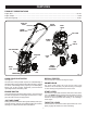
FEATURES PRODUCT SPECIFICATIONS Engine Size ...................................................................................................................................................................25.4cc Engine Output ..............................................................................................................................................................1.2 HP Sand Tank Capacity ....................................................................................................
ASSEMBLY UNPACKING WARNING: This product requires assembly. To prevent accidental starting that could cause serious personal injury, always disconnect the engine spark plug wire from the spark plug when assembling parts. Carefully remove the product and any accessories from the box. Make sure that all items listed in the packing list are included. Inspect the product carefully to make sure no breakage or damage occurred during shipping.
ASSEMBLY INSTALLING THE WHEEL ASSEMBLY ACCESSORY ADJUSTMENT KNOB See Figures 3 - 4. Use the wheel assembly accessory to transport the unit to and from the work area. To install: OPENING Raise the adjustment knob located at the back of the tine shield. Twist slightly to secure in the raised position. Insert the wheel assembly support rod into the opening beneath the adjustment knob. To place the wheels in a high position, insert the rod to the first hole.
ASSEMBLY WARNING: WARNING: Always shut off engine before fueling. Never add fuel to a machine with a running or hot engine. Move at least 30 ft. from refueling site before starting engine. Do not smoke! Gasoline and its vapors are highly flammable and explosive. To prevent serious personal injury and property damage, handle it with care. Keep away from ignition sources, handle outdoors only, do not smoke while mixing gasoline and oil together; and wipe up spills immediately.
ASSEMBLY ADDING SAND JUST ADD SAND™ LID See Figure 8. The cultivator is equipped with a Just Add Sand™ weight system, which improves the stability of the unit during operation. The added weight of the sand also helps you work with less effort and vibration. To add sand: Lift the lid of the Just Add Sand™ tank and remove. Pour dry sand into the tank. The tank will hold approximately 13 pounds of sand. NOTE: Be careful not to pour sand into or onto the engine housing. Replace Just Add Sand™ lid. Fig.
OPERATION Slowly push the primer bulb seven times. NOTE: If restarting a warm engine, do not push the primer bulb. Set the start lever to the START position. NOTE: If restarting a warm engine, leave the choke in the RUN position. Pull the starter cord until the engine runs. Return the starter cord gently to the starter housing. Do not allow the rope to snap back. Allow the engine to run for 15 seconds to warm up before using. Engage the throttle lever to operate.
OPERATION GENERAL CULTIVATING To dig more deeply, lift up on the handlebar. Apply downward pressure on the handlebar for more shallow cultivating. If the machine stays and digs in one spot, try rocking the unit from side to side to start it moving forward again. If the soil is very hard, water a few days before cultivating. Avoid working the soil when soggy or wet. Wait a day or two after heavy rain for the ground to dry. See Figure 14. Shallow cultivating less than 2 in.
ADJUSTMENTS WARNING: WHEEL SUPPORT POSITION A To prevent accidental starting that could cause serious personal injury, always disconnect the spark plug wire when making adjustments. ADJUSTING WHEEL POSITION See Figures 15 - 17. The wheel position of the unit is adjustable. Holes on the wheel support rod offer different heights to choose from in both the A and B positions. Install the wheel assembly accessory in position A to transport the cultivator to and from the work area. Fig.
MAINTENANCE CLEANING THE AIR FILTER WARNING: See Figure 19. Clean the air filter as indicated by the maintenance schedule. To clean the air filter: Loosen the air filter cover by turning the knob counterclockwise. When servicing, use only identical replacement parts. Use of any other parts may create a hazard or cause product damage. WARNING: Remove the air filter cover. Always wear safety goggles or safety glasses with side shields during power tool operation or when blowing dust.
MAINTENANCE REPLACING THE SPARK PLUG To replace the spark arrestor: Remove the five screws that hold the cover. See Figure 20. The cultivator uses Champion RCJ-4Y or NGK BPMR7A spark plug. Use an exact replacement and replace annually. Remove the spark plug boot. NOTE: Removing these screws requires the use of a T20 and T25 torx screwdriver. Remove the cover. Loosen the spark plug by turning it counterclockwise with a socket. Remove the muffler assembly and muffler gasket.
MAINTENANCE CLEANING THE EXHAUST PORT AND MUFFLER Air Filter: Depending on the type of fuel used, the type and amount of oil used, and/or your operating conditions, the exhaust port and muffler may become blocked with carbon deposits. If you notice a power loss with your gas powered tool, a qualified service technician will need to remove these deposits to restore performance. Cultivator Body: � Clean the air filter as previously described. Clean dirt, grass, and other materials from the entire unit.
TROUBLESHOOTING PROBLEM Engine fails to start. Engine hard to start. CAUSE REMEDY Engine switch is in the off position. Move switch to start. No fuel in tank. Fill tank. Spark plug shorted or fouled. Replace spark plug. Spark plug is broken (cracked porcelain or electrodes broken). Replace spark plug. Ignition lead wire shorted, broken, or disconnected from spark plug. Replace lead wire or attach to spark plug. Ignition inoperative. Contact authorized service center.
WARRANTY LIMITED WARRANTY STATEMENT B. Wear items – Bump Knobs, Outer Spools, Cutting Lines, Inner Reels, Starter Pulleys, Starter Ropes, Drive Belts, Tines, Felt Washers, Hitch Pins, Mulching Blades, Blower Fans, Blower and Vacuum Tubes, Vacuum Bag and Straps, Guide Bars, Saw Chains Techtronic Industries North America, Inc., reserves the right to change or improve the design of any RYOBI® brand outdoor product without assuming any obligation to modify any product previously manufactured.
WARRANTY THE FOLLOWING CALIFORNIA AIR RESOURCES BOARD (CARB) STATEMENT ONLY APPLIES TO MODEL NUMBERS REQUIRED TO MEET THE CARB REQUIREMENTS. TECHTRONIC INDUSTRIES NORTH AMERICA, INC., LIMITED WARRANTY STATEMENT FOR FEDERAL AND CALIFORNIA EMISSION CONTROL SYSTEMS NON-ROAD AND SMALL OFF-ROAD ENGINES YOUR WARRANTY RIGHTS AND OBLIGATIONS The U.S. Environmental Protection Agency (EPA), the California Air Resources Board (CARB), and Techtronic Industries North America, Inc.
WARRANTY Emissions Parts EMISSIONS MAINTENANCE SCHEDULE AND WARRANTED PARTS LIST Inspect Before Clean Every Replace Every Clean Every Each Use 5 Hours 25 Hours or Yearly 25 Hours or Yearly AIR FILTER ASSY INCLUDES: FILTER................................................................................ X ........................................... X SPARK SCREEN ...................................................................................................................................................
OPERATOR’S MANUAL CULTIVATOR RY60512 WARNING: The engine exhaust from this product contains chemicals known to the State of California to cause cancer, birth defects, or other reproductive harm. CALIFORNIA PROPOSITION 65 • SERVICE Now that you have purchased your tool, should a need ever exist for repair parts or service, simply contact your nearest Authorized Service Center. Be sure to provide all pertinent facts when you call or visit.