OPERATOR’S MANUAL MANUEL D’UTILISATION MANUAL DEL OPERADOR EDGER ATTACHMENT ACCESSOIRE COUPE-BORDURES ACCESORIO PARA RECORTAR BORDES RY15518 Your edger attachment has been engineered and manufactured to our high standard for dependability, ease of operation, and operator safety. When properly cared for, it will give you years of rugged, trouble-free performance. WARNING: To reduce the risk of injury, the user must read and understand the operator’s manual before using this product.
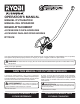
See this fold-out section for all of the figures r eferenced in the operator’s manual. Consulter l’encart à volets afin d’examiner toutes les figures mentionnées dans le manuel d’utilisation. Consulte esta sección desplegable para ver todas las figuras a las que se hace referencia en el manual del operador. Fig. 1 Fig. 4 A B K I H J C G D E Fig.
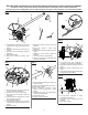
Fig. 7 Fig. 10 Fig. 9 A B A A B C D B A - Flange washer (rondelle de flasque, arandela de la brida) B - Slots (fentes, ranuras) C - Flange (flasque, brida) D - Gear case (carter d’engrenages, caja de engranajes) Fig. 8 B C D D C A A - 1/2 in. socket wrench (13 mm [1/2 po] clé à douilles, llave de boca tubular de 13 mm [1/2 pulg.
TABLE OF CONTENTS TABLE DES MATIÈRES / ÍNDICE DE CONTENIDO Introduction....................................................................................................................................................................... 2 Introduction / Introducción General Safety Rules.........................................................................................................................................................
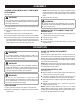
GENERAL SAFETY RULES WARNING: Read and understand all instructions. Failure to follow all instructions listed below may result in electric shock, fire, and/or serious personal injury. SAVE THESE INSTRUCTIONS Read these instructions and the instructions for the power head thoroughly before using the edger attachment. Know the tool. Read and understand the operator’s manual and observe the warnings and instruction labels affixed to the tool.
SPECIFIC SAFETY RULES Check the work area before each use. Remove all objects such as rocks, broken glass, nails, wire, or string which can be thrown or become entangled in the edger blade. Be sure all guards are properly and securely attached. Improper assembly can create a dangerous situation. Never stand or have any part of your body in line with the path of the edger blade. If the edger strikes any type of foreign object: Replace dull or worn blade; do not attempt to sharpen.
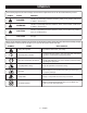
SYMBOLS The following signal words and meanings are intended to explain the levels of risk associated with this product. SYMBOL SIGNAL MEANING DANGER: Indicates an imminently hazardous situation, which, if not avoided, will result in death or serious injury. WARNING: Indicates a potentially hazardous situation, which, if not avoided, could result in death or serious injury. CAUTION: Indicates a potentially hazardous situation, which, if not avoided, may result in minor or moderate injury.
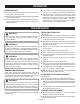
FEATURES PRODUCT SPECIFICATIONS Weight ....................................................................................... .....................................................................................4 lbs. Blade Length ................................................................................................................................................................... 9 in. Edging Depth..................................................................................................
ASSEMBLY JOINING THE POWER HEAD TO THE EDGER ATTACHMENT See Figure 3. NOTE: If the button does not release completely in the positioning hole, the shaft is not locked into place. Slightly rotate from side to side until the button is locked into place. Tighten the knob securely. WARNING: Never attach or adjust any attachment while power head is running. Failure to stop the engine or motor may cause serious personal injury. The edger attachment connects to the power head by means of a coupler device.
OPERATION OPERATING TIPS The edger will edge along sidewalks, driveways, flowerbeds, curbs, and similar areas. Use the arrow guide on the blade guard to align the blade with the edging surface. Cut at a steady pace. If the blade begins to bog down, you are edging too fast; slow your pace. Do not force the blade into ground. Light contact of the blade against the sidewalk edge, curb, etc., is acceptable and will not damage the edger. Best appearance is obtained when grass is dry.
WARRANTY LIMITED WARRANTY STATEMENT Techtronic Industries North America, Inc., warrants to the original retail purchaser that this RYOBI® brand outdoor product is free from defect in material and workmanship and agrees to repair or replace, at Techtronic Industries North America, Inc.’s, discretion, any defective product free of charge within these time periods from the date of purchase.
RÈGLES DE SÉCURITÉ GÉNÉRALES AVERTISSEMENT : Lire et veiller à bien comprendre toutes les instructions. Le non-respect de toutes les instructions ci-dessous peut entraîner un choc électrique, un incendie et/ou des blessures graves. CONSERVER CES INSTRUCTIONS Lire attentivement ces instructions et celles du moteur avant d’utiliser cet accessoire. Apprendre à connaître l’outil.
RÈGLES DE SÉCURITÉ PARTICULIÈRES Déblayer la zone de travail avant chaque utilisation. La débarrasser de tous les objets tels que cailloux, vere brisé, clous, fils métalliques, cordes, etc., risquant d’être projetés ou de se prendre dans la lame du coupe- bordures. S’assurer que tous les dispositifs de protection sont correctement et solidement fixés. Remplacer les lames émoussées ou usées; ne pas tenter de les affûter.
SYMBOLES Les termes de mise en garde suivants et leur signification ont pour but d’expliquer le degré de risques associé à l’utilisation de ce produit. SYMBOLE SIGNAL SIGNIFICATION DANGER : Indique une situation extrêmement dangereuse qui, si elle n’est pas évitée, aura pour conséquences des blessures graves ou mortelles. AVERTISSEMENT : Indique une situation potentiellement dangereuse qui, si elle n’est pas évitée, pourrait entraîner des blessures graves ou mortelles.
CARACTÉRISTIQUES FICHE TECHNIQUE Poids.................................................................................................................................................................... 1,8 kg (4 lb) Longueur de lame..........................................................................................................................................228,6 mm (9 po) Profondeur de chant.........................................................................
ASSEMBLAGE RACCORDEMENT DU BLOC MOTEUR À L’ACCESSOIRE COUPE-BORDURES Voir la figure 3. AVERTISSEMENT : Ne jamais installer ou ajuster un accessoire lorsque le moteur tourne. Ceci pourrait causer des blessures graves. L’accessoire coupe-bordures se raccorde au bloc-moteur à l’aide d’un dispositif de couplage. Débrancher le fil de la bougie ou débrancher de la prise secteur. Retirer le capuchon de suspension de l’accessoire Desserrer le bouton du coupleur de l’arbre du bloc moteur.
UTILISATION CONSEILS D’UTILISATION Le coupe-bordures permet d’effectuer la finition des trottoirs, allées et massifs de fleurs, terre-pleins et autres endroits semblables. À l’aide de la flèche de guidage placée sur le protègelame, aligner la lame avec le bord de la surface à finir. Couper à une vitesse régulière. Si la lame se met à peiner, c’est que la vitesse de travail est trop rapide; il faut la réduire. Ne pas forcer la lame dans la terre.
GARANTIE ÉNONCÉ DE LA GARANTIE LIMITÉE Techtronic Industries North America, Inc., garantit à l’acheteur original que ce produit RYOBI® est exempt de tous vices de matériaux ou de fabrication et s’engage à réparer ou remplacer gratuitement, à son choix, tout produit s’avérant défectueux au cours des périodes indiquées ci-dessous, à compter de la date d’achat.
REGLAS DE SEGURIDAD GENERALES ADVERTENCIA: Lea y comprenda todas las instrucciones. El incumplimiento de las instrucciones señaladas abajo puede causar descargas eléctricas, incendios y lesiones serias. GUARDE ESTAS INSTRUCCIONES Lea detenidamente estas instrucciones y las instrucciones para su cabezal motor antes de utilizar el accesorio de sopladora. Familiarícese con la herramienta.
REGLAS DE SEGURIDAD ESPECÍFICAS Despeje el área de trabajo cada vez antes de utilizar la herramienta. Retire todos los objetos como piedras, vidrio roto, clavos, alambre o cuerda que puedan salir disparados o enredarse en la cuchilla de la recortadora de bordes. Asegúrese de que todas las protecciones estén firmemente instaladas y de forma correcta. Si la cuchilla está desafilada o desgastada, cámbiela; no intente afilarla.
SÍMBOLOS Las siguientes palabras de señalización y sus significados tienen el objeto de explicar los niveles de riesgo relacionados con este producto. SÍMBOLO SEÑAL SIGNIFICADO PELIGRO: Indica una situación peligrosa inminente, la cual, si no se evita, causará la muerte o lesiones serias. ADVERTENCIA: Indica una situación peligrosa posible, la cual, si no se evita, podría causar la muerte o lesiones serias.
CARACTERÍSTICAS ESPECIFICACIONES DEL PRODUCTO Peso...................................................................................................................................................................... 1,8 kg (4 lb) Longitud de la cuchilla...............................................................................................................................228,6 mm (9 pulg.) Profundidad del recorte..............................................................
ARMADO ACOPLAMIENTO DEL CABEZAL DE POTENCI EL ACCESORIO PARA RECORTAR BORDES Vea la figura 3. ADVERTENCIA: Nunca una ni ajuste ningún accesorio mientras esté funcionando el cabezal motor. Si no se detiene el motor podría causar lesiones personales graves. El accesorio para recortar bordes se acopla al cabezal de potencia por medio de un dispositivo acoplador. Desconecte el cable de la bujía o desconecte la unidad del suministro de corriente. Retire la tapa de suspensión del accesorio.
FUNCIONAMIENTO Se logra el mejor aspecto cuando está seco el pasto. Evite cortar bordes en áreas donde esté húmeda la tierra o el pasto, o de lo contrario podría atascarse la protección de la cuchilla, con el consiguiente borde desigual resultante. Si se atasca la protección de la cuchilla, apague el motor, desconecte el cable de la bujía, o desconecte la unidad del suministro de corriente y limpie todos los desechos presentes en la protección de la cuchilla.
GARANTÍA DECLARACIÓN DE LA GARANTÍA LIMITADA Techtronic Industries North America, Inc. garantiza al comprador original al menudeo que este producto de la marca RYOBI® carece de defectos en los materiales y en la mano de obra, y acuerda reparar o remplazar, a la sola discreción de Techtronic Industries North America, Inc., cualquier producto defectuoso, sin cargo alguno al comprador, dentro de los siguientes períodos de tiempo a partir de la fecha de compra.
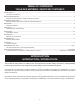
ILLUSTRATED PARTS LIST LISTE DES PIÈCES ILLUSTRÉES LISTA DE PIEZAS ILUSTRADAS 23 22 20 21 24 19 18 17 25 12 16 26 14 12 12 14 15 13 12 12 11 10 9 7 6 5 8 4 3 2 1 10
ILLUSTRATED PARTS LIST LISTE DES PIÈCES ILLUSTRÉES LISTA DE PIEZAS ILUSTRADAS KEY NO. Pièce Num. Núm. Ref. PART NO. DESCRIPTION Num. Réf. Núm. Pieza DESCRIPTION DESCRIPCIÓN QTY. Qté. Cant. 1 678018001 Blade Nut (M8, LH) Écrou de lame (M8, PG) Tuerca de la cuchilla (M8, MI) 1 2 638017001 Cupped Washer Rondelle bombée Arandela cóncava 1 3 638006008 Blade Lame Hoja 1 4 678011004 Flange Washer Rondelle à épaulement Arandela de brida 1 5 660887001 *Screw (10-24 x 5/8 in. Hex Hd.
NOTES / NOTAS 12
NOTES / NOTAS 13
OPERATOR’S MANUAL MANUEL D’UTILISATION / MANUAL DEL OPERADOR EDGER ATTACHMENT ACCESSOIRE COUPE-BORDURES ACCESORIO PARA RECORTAR BORDES RY15518 CALIFORNIA PROPOSITION 65 WARNING: This product and substances that may become airborne from its use may contain chemicals, including lead, known to the State of California to cause cancer, birth defects, or other reproductive harm. Wash hands after handling.