OPERATOR'S MANUAL CORDLESS DRILL-DRIVER MODEL NOS. HP1442M / HP1802M MODEL HP1442M 5 20 5 24 20 24 MODEL HP1802M THANK YOU FOR BUYING A RYOBI CORDLESS DRILL-DRIVER. Your new cordless drill-driver has been engineered and manufactured to Ryobi’s high standard for dependability, ease of operation, and operator safety. Properly cared for, it will give you years of rugged, trouble-free performance. CAUTION: Carefully read through this entire operator’s manual before using your new cordless drill-driver.
TABLE OF CONTENTS ■ General Safety Rule ................................................................................................................................................ 2-3 ■ Specific Safety Rules/Symbols ................................................................................................................................ 3-5 ■ Features ..............................................................................................................................................
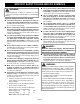
GENERAL SAFETY RULES Tool Use and Care ■ ■ ■ ■ ■ ■ ■ Use clamps or other practical way to secure and support the workpiece to a stable platform. Holding the work by hand or against your body is unstable and may lead to loss of control. Do not force tool. Use the correct tool for your application. The correct tool will do the job better and safer at the rate for which it is designed. Do not use tool if switch does not turn it on or off.
SPECIFIC SAFETY RULES AND/OR SYMBOLS ■ WARNING: A damaged battery is subject to explosion. To avoid serious personal injury, properly dispose of a damaged battery. ■ Important Safety Instructions For Charger ■ ■ ■ ■ ■ ■ ■ ■ Save these instructions. This manual contains important safety and operating instructions for charger. Following this rule will reduce the risk of electric shock, fire, or serious personal injury.
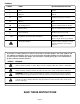
SYMBOLS SYMBOL NAME DESIGNATION/EXPLANATION V Volts Voltage A Amperes Current Hz Hertz Frequency (cycles per second) min Minutes Time Alternating Current Type or a characteristic of current --- Direct Current Type or a characteristic of current n0 No Load Speed Rotational speed, at no load .../min Revolutions or Reciprocation Per Minute Revolutions, strokes, surface speed, orbits etc. per minute Safety Alert Symbol Indicates danger, warning or caution.
FEATURES PRODUCT SPECIFICATIONS: DRILL-DRIVER HP1442M HP1802M Chuck 3/8 in. Keyless 1/2 in. Keyless Motor DC Motor 14.4 Volt DC Motor 18 Volt Gear Train Two Speed Two Speed Switch Variable Speed Variable Speed No Load Speed 0-330 RPM (Low) 0-350 RPM (Low) 0-1100 RPM (High) 0-1300 RPM (High) Clutch 24 Positions 24 Positions Charger Input 120 V, 60 Hz, AC only 120 V, 60 Hz, AC only Charge Rate 1 Hour 1 Hour KNOW YOUR DRILL-DRIVER SWITCH LOCK See Figure 1.
FEATURES MODEL HP1442M TWO SPEED GEAR TRAIN (HI-LO) BIT STORAGE AREA 20 24 TORQUE ADJUSTMENT RING LEVEL DIRECTION OF ROTATION SELECTOR 5 KEYLESS CHUCK SWITCH TRIGGER MAG TRAY™ (SCREW HOLDER) TOP VIEW OF LEVEL FOR HORIZONTAL DRILLING BATTERY PACK END VIEW OF LEVEL FOR VERTICAL DRILLING Fig.
OPERATION WARNING: GREEN LIGHT "ON" INDICATES FULLY CHARGED If any parts are missing, do not operate tool until the missing parts are replaced. Failure to do so could result in possible serious personal injury. BATTERY CHARGER LED FUNCTION OF CHARGER See Figure 2. LED WILL BE LIGHTED TO INDICATE STATUS OF CHARGER AND BATTERY PACK: ■ Red LED lighted = Fast Charging Mode ■ Green LED lighted = Fully Charged Battery Pack ■ Yellow and Green LED Lighted = Control Charge or Defective Battery Pack.
OPERATION SWITCH REVERSE DIRECTION OF ROTATION SELECTOR 24 See Figure 4. Your drill starts and stops by depressing and releasing the switch trigger. Release the switch trigger to turn drill OFF. 20 VARIABLE SPEED SWITCH LOCK See Figure 4. The switch trigger can be locked in the OFF position. This feature helps reduce the possibility of accidental starting when not in use. To lock the switch trigger, place the direction of rotation selector in the center position. 5 See Figure 4.
OPERATION KEYLESS CHUCK 24 CHUCK COLLAR 20 RELEASE (UNLOCK) 5 See Figure 6. A keyless chuck has been provided with your drill to allow for easy installation and removal of bits. As the name implies, you can hand tighten or release drill bits in the chuck jaws. Grasp and hold the collar of the chuck with one hand. Rotate the chuck body with your other hand. The arrows on the chuck indicate which direction to rotate the chuck body in order to GRIP (tighten) or RELEASE (unlock) the drill bit.
OPERATION INSTALLING BITS CHUCK BODY DRILL BIT 20 24 ■ Place the direction of rotation selector in center position. This will lock the switch trigger in the off position. See Figure 4. ■ Open or close the chuck jaws to a point where the opening is slightly larger than the bit size you intend to use. Also, raise the front of your drill slightly to keep the bit from falling out of the chuck jaws. ■ Insert your drill bit into the chuck the full length of the jaws. See Figure 8.
OPERATION SCREWDRIVING TORQUE ADJUSTMENT The proper setting depends on the type of material and the size of screw you are using. 20 24 TO DECREASE TORQUE 5 (Driving power of your drill-driver) When using your drill-driver for various driving applications, it becomes necessary to increase or decrease the torque in order to help prevent the possibility of damaging screw heads, threads, workpiece, etc. In general, torque intensity should correspond to the screw diameter.
OPERATION WARNING: LEVEL Always wear safety goggles or safety glasses with side shields when operating tool. Failure to do so could result in objects being thrown into your eyes, resulting in possible serious injury. DRILLING END VIEW 20 WARNING: 15 See Figure 14. When drilling hard, smooth surfaces, use a center punch to mark the desired hole location. This will prevent the drill bit from slipping off center as the hole is started.
OPERATION TO RETIGHTEN A LOOSE CHUCK MALLET KEYLESS CHUCK CHUCK JAWS 20 24 See Figures 15, 16, and 17. ■ Lock the switch trigger by placing the direction of rotation selector in center position. See Figure 4. ■ Insert a 5/16 inch or larger hex key wrench into the chuck of your drill and tighten the chuck jaws securely. ■ Tap the hex key wrench sharply with a mallet in a clockwise direction. See Figure 15. This will loosen the screw in the chuck for easy removal.
MAINTENANCE DO NOT ABUSE POWER TOOLS. Abusive practices can damage the tool, as well as the workpiece. WARNING: When servicing use only identical Ryobi replacement parts. Use of any other parts can create a hazard or cause product damage. Avoid using solvents when cleaning plastic parts. Most plastics are susceptible to damage from various types of commercial solvents and may be damaged by their use. Use a clean cloth to remove dirt, oil, grease, etc.
OPERATOR'S MANUAL CORDLESS DRILL-DRIVER MODEL NOS. HP1442M / HP1802M • SERVICE Now that you have purchased your tool, should a need ever exist for repair parts or service, simply contact your nearest Ryobi Authorized Service Center. Be sure to provide all pertinent facts when you call or visit. Please call 1-800-525-2579 for your nearest Ryobi Authorized Service Center. You can also check our web site at www.ryobitools.com for a complete list of Authorized Service Centers. • MODEL NO. AND SERIAL NO.