OPERATOR’S MANUAL CORDLESS DRILL-DRIVER MODEL NOS. SA960 / SA120 MODEL SA960 20 20 MODEL SA120 This new drill has been engineered and manufactured to our Ryobi’s high standard for dependability, ease of operation, and operator safety. When properly cared for, the drill will give you years of rugged, trouble-free performance. WARNING: To reduce the risk of injury, the user must read and understand the operator’s manual before using this product. Thank you for buying a Ryobi product.
TABLE OF CONTENTS ■ Introduction .................................................................................................................................................................... 2 ■ General Safety Rules .................................................................................................................................................. 3-4 ■ Specific Safety Rules .............................................................................................................
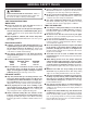
GENERAL SAFETY RULES ■ Remove adjusting keys or wrenches before turning the tool on. A wrench or a key that is left attached to a rotating part of the tool may result in personal injury. ■ Do not overreach. Keep proper footing and balance at all times. Proper footing and balance enable better control of the tool in unexpected situations. ■ Use safety equipment. Always wear eye protection. Dust mask, non-skid safety shoes, hard hat, or hearing protection must be used for appropriate conditions.
GENERAL SAFETY RULES ■ When servicing a tool, use only identical replacement parts. Follow instructions in the Maintenance section of this manual. Use of unauthorized parts or failure to follow Maintenance Instructions may create a risk of shock or injury. SERVICE ■ Tool service must be performed only by qualified repair personnel. Service or maintenance performed by unqualified personnel may result in a risk of injury.
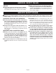
IMPORTANT SAFETY INSTRUCTIONS FOR CHARGER WARNING: Read and understand all instructions. Failure to follow all instructions listed below, may result in electric shock, fire and/or serious personal injury. ■ Never use a battery that has been dropped or received a sharp blow. A damaged battery is subject to explosion. Properly dispose of a dropped battery immediately. Failure to heed this warning can result in serious personal injury. ■ Save these instructions.
SYMBOLS Important: Some of the following symbols may be used on your tool. Please study them and learn their meaning. Proper interpretation of these symbols will allow you to operate the tool better and safer.
SPECIFICATIONS DRILL-DRIVER SA960 SA120 Chuck 3/8 in. (10 mm) Keyless 3/8 in. (10 mm) Keyless Motor DC Motor 9.6 Volt DC Motor 12 Volt Switch Variable Speed Variable Speed No Load Speed 0 - 550 RPM 0 - 550 RPM Clutch 24 Positions 24 Positions Charger Input 120 V, 60 Hz, AC only 120 V, 60 Hz, AC only Charge Rate 3-6 Hours 3-6 Hours Torque Maximum 90 in.lb. Maximum 95 in.lb. UNPACKING INSTRUCTIONS When unpacking the tool: ■ Carefully remove the tool and accessories from the box.
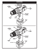
FEATURES KNOW YOUR DRILL-DRIVER SWITCH LOCK See Figure 1. Before using this tool, familiarize yourself with all operating features and safety requirements. However, do not let familiarity with the tool make you careless. The switch trigger can be locked in the OFF position. This feature helps reduce the possibility of accidental starting when not in use. WARNING: FORWARD/REVERSE SELECTOR (DIRECTION OF ROTATION SELECTOR) The drill-driver has a forward/reverse selector located above the switch trigger.
FEATURES MODEL SA960 LEVEL TORQUE ADJUSTMENT RING 20 BIT STORAGE AREA DIRECTION OF ROTATION SELECTOR SWITCH TRIGGER KEYLESS CHUCK BATTERY PACK MODEL SA120 LEVEL TORQUE ADJUSTMENT RING 20 BIT STORAGE AREA DIRECTION OF ROTATION SELECTOR SWITCH TRIGGER KEYLESS CHUCK BATTERY PACK MAG TRAY™ Fig.
ADJUSTMENTS REVERSIBLE REVERSE DIRECTION OF ROTATION SELECTOR 5 10 See Figure 2. This tool has the feature of being reversible. The direction of rotation is controlled by a selector located above the switch trigger. With the drill held in normal operating position, the direction of rotation selector should be positioned to the left of the switch for drilling. The drilling direction is reversed when the selector is to the right of the switch.
ADJUSTMENTS INSTALLING BITS CHUCK JAWS CHUCK BODY DRILL BIT 20 CHUCK COLLAR RIGHT Fig. 4 20 See Figures 4 and 5. ■ Lock the switch trigger by placing the direction of rotation selector in center position. See Figure 9. ■ Open or close chuck jaws to a point where the opening is slightly larger than the bit size you intend to use. Also, raise the front of the drill slightly to keep the bit from falling out of the chuck jaws. ■ Insert drill bit straight into chuck the full length of the jaws.
ADJUSTMENTS ADJUSTABLE TORQUE CLUTCH TO DECREASE TORQUE 20 See Figure 6. When using your drill-driver for various driving applications, it becomes necessary to increase or decrease the torque in order to help prevent the possibility of damaging screw heads, threads, workpiece, etc. In general, torque should correspond to the intensity of the screw diameter. If the torque is too high or the screws too small, the screws may be damaged or broken. The torque is adjusted by rotating the torque adjustment ring.
OPERATION BATTERY PACK WARNING: Do not allow familiarity with the drill-driver to make you careless. Remember that a careless fraction of a second is sufficient to inflict severe injury. CHARGING ASSEMBLY CHARGING YOUR DRILL-DRIVER The battery pack for this tool has been shipped in a low charge condition to prevent possible problems. Therefore, you should charge it overnight prior to use. Note: Batteries will not reach full charge the first time they are charged.
OPERATION IMPORTANT INFORMATION FOR RECHARGING HOT BATTERIES 10 DIRECTION OF ROTATION SELECTOR 5 When using your drill-driver continuously, the batteries become hot. You should let the batteries cool down for approximately 30 minutes before attempting to recharge. NOTE: This situation occurs when continuous use of your drill-driver causes the batteries to become hot. It does not occur under normal circumstances.
OPERATION VARIABLE SPEED See Figure 9. Your drill has a variable speed feature in the switch. The switch delivers higher speed and torque with increased trigger pressure. Speed is controlled by the amount of switch trigger depression. WARNING: 15 20 Always wear safety goggles or safety glasses with side shields when operating tool. Failure to do so could result in objects being thrown into your eyes, resulting in possible serious injury. DRILLING See Figure 11.
OPERATION LEVEL DRILLING 20 See Figure 12. A convenient new feature provided with your drill is a level. It is recessed in the motor housing on top of your drill. It can be used to keep drill bit level during drilling operations. MAG TRAY™ MODEL SA120 20 See Figure 13. For convenience, your drill has a Mag Tray™ to place small parts when doing a variety of tasks. LEVEL Fig. 12 20 MODEL SA120 MAG TRAY ™ (SCREW HOLDER) Fig.
MAINTENANCE MALLET WARNING: KEYLESS CHUCK When servicing use only identical Ryobi replacement parts. Use of any other parts may create a hazard or cause product damage. CHUCK JAWS 20 Do not abuse power tools. Abusive practices can damage tool as well as workpiece. WARNING: Do not at any time let brake fluids, gasoline, petroleum-based products, penetrating oils, etc. come in contact with plastic parts. They contain chemicals that can damage, weaken or destroy plastic.
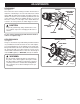
MAINTENANCE ■ Open the chuck jaws and remove the hex key. Remove the chuck screw by turning it in a clockwise direction. See Figure 15. NOTE: The screw has left hand threads. Insert the hex key in the chuck and tighten chuck jaws securely. Tap sharply with a mallet in a counterclockwise direction. This will loosen the chuck on the spindle. It can now be unscrewed by hand. See Figure 16. TO RETIGHTEN A LOOSE CHUCK The chuck may become loose on spindle and develop a wobble.
NOTES Page 19
OPERATOR’S MANUAL CORDLESS DRILL-DRIVER MODEL NOS. SA960 / SA120 • SERVICE Now that you have purchased your tool, should a need ever exist for repair parts or service, simply contact your nearest Ryobi Authorized Service Center. Be sure to provide all pertinent facts when you call or visit. Please call 1-800-525-2579 for your nearest Ryobi Authorized Service Center. You can also check our web site at www.ryobitools.com for a complete list of Authorized Service Centers. • MODEL NO. AND SERIAL NO.