
PV Kit 2.0 Edge Manual

The right way to attach almost anything to metal roofs!
800.284.1412 www.lmcurbs.com
PV Kit 2.0 Installation Instructions
These instructions are for use by those experienced in the trade. Always follow appropriate safety precautions and use appropriate tools.
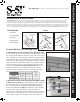
1. Install the rst row of S-5! brackets, at the edge of the
array: It is critical that this row is straight. Install a bracket at
both ends of the row, by measuring from a reference point such
as the eave of the roof. Stretch a string line between the brackets
to provide a true line to mount the remaining edge brackets
(Fig. 1). Secure the RibBracket directly into the crown of the roof
prole by driving the included fasteners into the pre-punched
holes. To achieve tested holding strength, secure the RibBracket
by using all pre-punched hole locations. Drive the fastener in
until it is tight and the washer is rmly seated. Be careful not
to over-drive fasteners. A slight extrusion of rubber around the
washer is a good visual-tightness check. Please see S-5! bracket
installation instructions for specic install information.
To install PV Kit 2.0 On Exposed Fastener
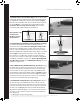
2. Mount the PV Disks and the EdgeGrab/StandO Assembly
to the rst row of brackets: place the PV Disk atop the brackets
and thread the male portion of the StandO through the disk
and into the M8 nut inserted in the bracket (nut provided with
brackets). Drive the EdgeGrab/StandO assembly down with
the provided bit tip (Fig. 2) until the base of the Stand-O seats
the disk in place and breaks the thread locking seal between the
StandO and the Low Prole Bolt. Leave the grab up, to allow
space for a module frame. A 1/2” open end wrench can be used
to further tighten the StandO atop the disk if desired.
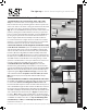
3. Install the rst row of modules (Fig 3a): Place the rst
module in the grabs pushing on the frame to seat the module
against the EdgeGrabs and Module Placement Bevel Guide (Fig
3b). Drive the Low Prole Bolt with the provided Hex Bit Tip to
tighten the grabs (Fig 3c On Previous Page). Low Prole Bolt
and Stando should be torqued to 120-130 in lbs (13.6-14.7
Nm). Check torque periodically with Calibrated Dial Torque
Wrench.
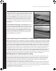
4. Install MidGrab/StandO Assembly & PV Disk on Brackets:
the PV Disk and MidGrab/StandO Assembly should be mounted
to the brackets before mounting the brackets to the roof.
Place the PV Disk atop the brackets and thread the male portion
of the StandO through the disk and into the M8 nut inserted in
the bracket (nut provided with brackets). Drive the EdgeGrab/
StandO assembly down with the provided bit tip until the base
of the Stand-O seats the disk in place (Fig 4) in similar fashion
to Step 2. Note: When using CorruBrackets, the bracket must
be secured to the roof prior to xing the S-5-PV Kit 2.0 EdgeGrab
or MidGrab assembly to bracket. See: Tips for Mounting with
CorruBrackets, S-5-H90, or S-5 K Grip Style Clamps at end of
installation instructions.
1.
2.
3a.
4.
3b.