
PV Kit 2.0 Edge Manual

5. Place MidGrab/StandO/Disk & Bracket Assemblies:
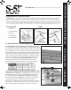
Using the PV module as a guide, place the bracket on the rib
and move into place so that the edge of the module is seated
against the wall of the MidGrab and the Module Placement
Bevel Guide (Fig. 3b). Secure the RibBracket directly into the
crown of the roof prole by driving the fasteners (included
with RibBrackets) into the pre-punched holes as described
in step 1 above. At this point the grabs should be left in the
open position, at least partially to accommodate the next row
of modules.
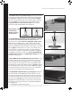
6. Install Additional PV Modules-repeating steps 3-5: place
another module in the MidGrabs that were left open in the
previous step. Tighten the downslope row of grabs each time
a module is placed and leave the upslope MidGrabs open
until the next module is placed (Fig. 6). The nal row will be
nished with EdgeGrab/StandO Assemblies. Periodically
look back at the modules you’ve installed to double check
that the MidGrabs were tightened.
PV Kit 2.0 Installation Instructions
S-5!® Warning! Please use this product responsibly!
Products are protected by multiple U.S. and foreign patents. For published data regarding holding strength, fastener torque, patents, and trademarks, visit the S-5! website at www. S-5.com.
Copyright 2018, Metal Roof Innovations, Ltd. S-5! products are patent protected. S-5! aggressively protects its patents, trademarks, and copyrights.
PV20-V1.1-01/18
5.
6.
Wire Management and Bonding and Grounding
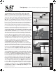
UL Listed PV wire clips should be used to attach excess wire to the underside of module frames. Clip
the wires to the frame before installing the module, so that the leads are positioned correctly. Clips
should be placed often enough so that the wire cannot sag and touch the roof. The home run and
any other exposed wire should be encased and routed through conduit. The conduit should be
intermittently attached to the roof with S-5 clamps or brackets.
Module frames within each column are bonded and have an established ground path through the PV
Disk. Adjacent columns of modules should be bonded together with a jumper; a UL listed grounding
lug should be attached to a module frame at the edge of the array to attach a ground wire for the array.
Tips for Mounting with CorruBrackets, S-5-H90/H90 Mini, S-5-K Grip/K grip Mini
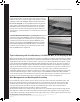
When mounting with any S-5! CorruBracket, S-5-H90, S-5-K Grip style clamps, steps 4/5 will vary slightly.
The fasteners for clamp or bracket to the roof must be installed before the PV Disk is mounted atop the
clamp/bracket. The module can still be used as a spacer to place the clamps/brackets. Prepare a clamp
or bracket with the full MidGrab/StandO Assembly & PV Disk mounted atop it. Place this assembly so
that the inside of the midgrab and the Module Placement Bevel Guide on the PV Disk rest against the
edge of the module seating it in place as described in step 5 and shown in Fig 3b. Use a marker (do not
use graphite pencil) to mark the location of the clamp or bracket on the roof. Now remove the pre-
assembled clamp/bracket and PV Kit 2.0 and mount a clamp or bracket without the PV Kit, on the mark
you made. After fastening the clamp or bracket in place, the MidGrab/StandO Assembly & PV Disk
can be mounted atop it. The slotted hole atop the bracket allows the kit to be slid out of the way as the
module is placed, then pushed into place against the edge of the module and tightened.