
User's Manual
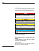
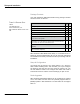
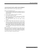


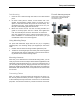
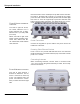
Table Of Contents

10 S&C Instruction Sheet 1069-500
antenna 2antenna 1 antenna 3
radio 1
Setup and Installation
Note the location of the weatherproof cap that has the reset but-
ton under it, at bottom left in Figure 3.3. To reset the unit, apply
power and wait until the unit has fully booted and the status light
has come on. Then use a paperclip to press and hold the reset
button until the status LED blinks. This takes about 12 to 15 sec-
onds.
Power Connection
Connect the suppled AC power cable to AC power and to the
IntelliCom 1720 radio.
Powering Other Ethernet Devices
Ports 2 and 3 can provide IEEE 802.3af Power over Ethernet
(PoE) functionality to Powered Devices (PD) connected to these
ports. Port 1 cannot.
Connecting Antennas
When connecting antennas, connect them in numerical order
1-2-3. If you are not using three antennas per radio, do not ‘skip’
antenna connectors.
port 1port 2port 3dc power usbac power
power status radio 1 radio 2 ethernet
–mesh–
Figure 3.5 Power and Ethernet
Connectors
From left to right: AC Power,
DC Power, Ethernet Port 3
(PoE), Ethernet Port 2 (PoE),
Ethernet Port 1 (no PoE), USB
(not used).
Below, from left to right: reset
button (under threaded cap),
Power LED, Status LED, Ra-
dio 1 Mesh LED, Radio 2 Mesh
LED, Ethernet.
Figure 3.6 Antenna Connectors
From left to right: Antenna 1,
Antenna 2, Antenna 3. The an-
tenna 1 connector is at the top
of the unit (farthest from the
power and Ethernet connec-
tions) on both the left and right
side.