
User's Manual
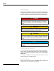
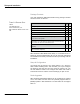

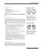

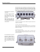
Table Of Contents

S&C Instruction Sheet 1069-500 7
Tools Needed
You will need:
• #2 Phillips screwdriver.
• Small adjustable wrench.
• Wire cutters to cut tie wraps around cables.
• Weatherproofing kit
Depending on the installation location, you may need ladders, a
lift truck, or other means to access the actual installation loca-
tions.
Preparing Earth Ground
The S&C IntelliCom WAN 1720 mesh radio must be properly con-
nected to earth ground. Failure to do so may result in equipment
damage, injury, or death. The product warranty does not cover
damages resulting in part or in whole from improper grounding.
Consult your location’s building and electrical codes regarding
antennas and follow them, or consult the National Electric Code
(NEC).
• If connecting to a tower or pole, connect the base of the
tower pole directly to the building’s ground or to one or more
approved grounding rods using 10 AWG ground wire and
corrosion-resistant connectors.
• Connect the grounding cable to rain gutters only if the
rain gutter is connected to earth ground.
• Ground rods should be copper-plated, 1.8 - 2.4 m (6 - 8 ft)
long.
• Install all grounding components in straight lines. If bends are
unavoidable, do not make sharp turns.
• Earth-to-ground should not be more than 10 ohms.
• Understanding the soil is very important in order to create a
proper earth ground. If your soil is rocky or sandy, drive your
ground rods and then pull them back out and dump an ap-
proved ground enhancement material into the holes where the
grounding rods go. Then replace the grounding rods. Keep in
mind that some salt compounds are corrosive and can cause
copper to corrode.
Antenna Placement
S&C recommends the use of antennas specifically designed for
MIMO applications. While it is possible to select and mount six
individual antennas, determining correct placement and spacing
is difficult. Use an antenna engineered for best results with MIMO.
Setup and Installation
Figure 3.1 S&C IntelliCom
WAN 1720 AC Connector
1-neutral2-line
3-ground
AC Power
Cable-End View
1-neutral 2-line
3-ground
AC Power
Connector View
This shows the pinout of the
AC Power connector used on
outdoor nodes. Views are shown
of both the connector on the unit,
and the mating connector on the
cable itself. Pin 1 is neutral; pin 2
is line, and pin 3 is ground.
Figure 3.2 S&C IntelliCom
WAN 1720 DC Connector
5
6
1
2
ground
power
Cable-End View
5
6
1
2
Connector View
3
4
3
4
power
This shows the pinout of the DC
power connector used on outdoor
nodes. Each view is of the cable
connector, as viewed end-on.
Pins 3 and 4 are ground. Pins 1
and 2 are +12VDC power.