
User's Manual


E-8
Make sure to unplug the AC power cord before
installing the sound bar or changing the position.
To mount the sound bar on the wall
Caution:
● Be very careful to prevent the sound bar [3.8 lbs.
NJ@IURPIDOOLQJZKHQPRXQWLQJRQWKHZDOO
● %HIRUHPRXQWLQJFKHFNWKHZDOOVWUHQJWK'RQRW
put on the veneer plaster or whitewashed wall. The
VRXQGEDUPD\ IDOO,IXQVXUHFRQVXOWDTXDOL¿HG
service technician.
● Mounting screws are not supplied. Use appropri-
ate ones.
● Check all wall mount angle screws for looseness.
● Select a good location. If not, accidents may occur
or the sound bar may get damaged.
● SHARP/Hisense are not responsible for acci-
dents resulting from improper installation.
■ Driving screws
SHARP designed the sound bar so you may hang
it on the wall. Use proper screws (not supplied).
See below for size and type.
1/8” (3.2 mm)
3/8” (9 mm)
Min. 7/8” (22 mm)
3/16”
(5 mm)
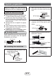
■ Installing the sound bar
1 Fix the pattern paper to the wall in hori-
]RQWDOSRVLWLRQDVEHORZ
44 mm
509 mm
Wall surface
Pattern paper
(supplied)
21-5/8” (548 mm)
2 Make a hole on the wall following the screw
point marks on the pattern paper by using
a drill.
Wall surface
1-1/4” (32 mm)
3/8” (8-9 mm)
3 Fix a wall mount plug into the hole using
D KDPPHU XQWLO LW LV ÀXVK ZLWK WKH ZDOO
surface.
1-1/4” (32 mm)
3/8” (8-9 mm)
Wall sur
face
4 Fasten the screws to the wall as shown below.
7RWDOVFUHZLVSLHFHV
Wall surface
Wall surface
Screw using
screwdriver
3/16” (4.5 mm - 5 mm)
Gap from wall
surface
5 Hang the sound bar onto the screws.
System preparation