
Specifications


LIT-FBX1200/2400-OP-EN-050817.pmd - rr
3
© 2005 Sabine, Inc.
SECTION TWO — APPLICATIONS
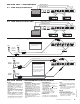
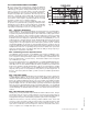
2.2. FBX Setup for Entire Mix
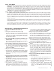
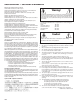
2.1. FBX Setup for Monitors
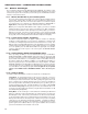
2.3. FBX Setup for Single Insert Point
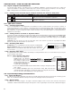
2.4. FBX Setup for Insert Send & Return
Right Main Send
Left Main Send
Ch. B
IN
Ch. A
IN
All other Signal
Processing
Ch. B
OUT
Ch. A
OUT
FILTERS
• 12 independent digital notch fil-
ters per channel, controlled auto-
matically from 40 Hz to 20 KHz.
• Filter width: user-controllable - ei-
ther 1/10 or 1/5 octave*, constant "Q"
• Resolution: 1 Hz
• Time required to find and eliminate
feedback: 0.4 seconds, typical @ 1
KHz
• Number of Dynamic vs. Fixed fil-
ters per channel: user selectable.
Last configuration stored in memory.
INPUT/OUTPUT**
• Input/Output Maximum Signal
Levels: Balanced +27dBV peak, un-
balanced +21 dBV peak
• Output Drive: Unit will perform as
specified driving a load >600 Ohms
• Input Impedance: Balanced or un-
balanced >40K Ohms, PIN 2 high
• Output Impedance: Balanced or un-
balanced 150 Ohms nominal, PIN 2
high
• Bypass: True power off bypass
• Headroom: +23 dB peak @ 4 dBV
nominal input, balanced
• I/O Connectors: XLR-3 and 1/4"
TRS
PERFORMANCE***
• Frequency response: 20 Hz – 20
KHz +/- 0.3 dB
• Gain matching: +/- 0.2 dB
• Spectral Variation: + .25 dB, 20
Hz to 20 KHz
• SNR - Dynamic Range: >100 dB
• THD: .005% at 1 KHz
< 0.01% 20 Hz – 10 KHz
< 0.025% 10 KHz – 20 KHz
• Dynamic Range: >105 dB
POWER INPUT
• 115 VAC: 100 – 130 VAC 50/60 Hz
• 230 VAC: 200 – 240 VAC 50/60 Hz
FUSE
• 115 VAC, 0.1 A, 10 W, 0.160 A SB fuse
• 230 VAC, 0.06A, 10 W, 0.080 A T fuse
DIMENSIONS
• 1-U rack mount; 19 x 1.75 x 6.25 in.
nominal (rack mountable); 48.3 x
4.5 x 15.9 cm nominal
WEIGHT
• 8.0 lbs. (3.6 kg) nominal
OPERATING TEMPERATURE
• Safe operating temperature: -15 to
+50 degrees centigrade ambient
temperature (5 to 122F)
SECTION THREE — ENGINEERING SPECIFICATIONS
TS or TRS Connectors
Ch. B OUT
Ch. A OUT
Ch. B IN
Ch. A IN
TS or TRS Connectors
Ch. 2
<>
Insert
Send
Insert
Return
Ch. 1
<>
Insert
Send
Insert
Return
IMPORTANT NOTE
• Use a ¼-inch TRS plug for
balanced sends/inserts.
• Use a ¼-inch TS plug for
unbalanced sends/inserts.
• Mixing balanced and unbal-
anced connections may result
in a 6 dB loss of gain.
< Low Z >
< High Z >
< Insert >
Ch. 1 Ch. 2
TRS Connector
TRS Connector
Y Insert Cords (TRS to TS + TS)
Ch. B OUT Ch. B IN Ch. A IN
TS "Y" Connector
Ch. A OUT
TS "Y" Connector
Monitor Mix 1
Monitor Mix 2
Ch. B
IN
Ch. A
IN
Ch. B
OUT
Ch. A
OUT
Tests performed using an Audio Precision
System One model 322 or equal.
*Below approximately 200 Hz the feedback filters
become slightly wider to increase the feedback and
rumble capture speed at these low frequencies.
IMPORTANT NOTE
• Mixing balanced and unbal-
anced connections may result
in a 6 dB loss of gain.