SABINE the sound of innovation 13301 US Highway 441 Alachua, FL 32615 Phone (386) 418-2000 Fax (386) 418-2001 www.Sabine.
Summary of Features SSection ::AAppendices EC N-Nine D eclaration of Conformity ection ine ppendices Declaration of Conformity EC - DECLARATION OF CONFORMITY CE Marking SABINE, INC.
Summary of Features NAVIGATOR SERIES: • Front Panel Controlable • Line Inputs • Remote Control Wall Panel Ready • Ethernet Control Ready NAV240-U (2 x 4 System Processor) NAV360-U (3 x 6 System Processor) NAV4802-U (4 x 8 System Processor) NAV8802-U (8 x 8 System Processor) NAVIGATOR S SERIES: • No Front Panel Control (for security) • Mic / Line inputs • Remote Control Wall Panel • Ethernet Control Ready NAV240-S (Blank Front 2 x 4 System Processor)
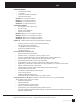
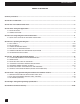
Table of Contents Table of Contents Notes Summary of Features............................................................................................................................................................5 Section One: Introduction....................................................................................................................................................7 Section Two: Front & Back Panel Views...............................................................................
Section One: Introduction Section One: Introduction Congratulations on your purchase of the Sabine Navigator. These products are our latest versions of the popular Navigator System Processors. The new Navigators come in four basic input/output configurations. The NAV240 is a 2 by 4 , the NAV360 is a 3 by 6, the NAV4802 is 4 by 8, and the NAV8802 is an 8 by 8.
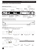
Section Two: Front & Back Panel Views Section Two: Front & Back Panel Views NAV240 Front Panel Data wheel Edits parameter values Menu keys Cursor keys Scroll through Moves cursor through available menus available parameters Typical - all front panel control units follow this scheme EDIT Button Engages Channel Edit mode USB Connector Connect your computer for software control RS232 Serial Connector Connect your computer for software control Input & Output signal indicators Channel Select Buttons Sele
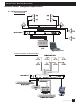
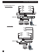
Section Three: Navigator Applications Section Three: Navigator Applications 3.1 Installed Audio House of Worship NAV4802 Laptop Control Conference Room - Distributed Audio NAV8802 9 Navigator2_OperatingGuide110928.
Section Three: Navigator Applications 3.
Section Four: Using Navigator Controls Section Four: Using Navigator Front Panel Controls 4. 2. 7. 5. 8. NAV4802 3. BLUE Edit LED for each channel 1. 6. 9. 10. 11. RED Mute LED for each channel 1. MUTE Button: Select this to turn the Channel Select Buttons into MUTE buttons. Each press of a Channel Select button toggles that channel’s Mute Status, and the RED Mute LED will light indicating the channel is muted. 2. EDIT Button: Select this to turn the Channel Select Buttons into EDIT buttons.
Section Four: Using Navigator Controls 4.1. Getting Started with the Navigator Front Panel · After powering up the unit, the following initialization screen is displayed on the LCD: NAV4802* · The initialization process takes about 8 seconds and during that period the unit boots and displays the Navigator firmware version. · After the initialization process is finished the Navigator displays its main creen: NAV4802* · The screen shows the current program number and program name assigned to the unit.
Section Five: Operating the Navigator Section Five: Operating the Navigator 5.1 Input menus Each of the Navigator input channels has a separate Menu key. There are 7 function menus for each input channel, and you cycle through these by pressing the Menu keys. The first line in the LCD indicates which input channel you are editing, and shows the name of that channel if you have added one (for example, IN_1: ____), The menus are arranged in a linear fashion.
Section Five: Operating the Navigator FBX Feedback Exterminator NAV4802 & NAV8802 FBX NAV240, 360 See Section 5.6 for a complete description of how to operate the FBX Feedback Exterminator · EQ#: Selects one of the 8 available FBX filters. · TYPE: Choose Fixed for more gain before feedback, Dynamic for control of new feedback during the show. See section 5.5 for a complete guide to using the FBX function. · LVL: Shows level in dB of the FBX filter (not editable).
Section Five: Operating the Navigator FBX-Mode NAV4802 & NAV8802 NAV240, 360 · SETUP MODE: This screen is used to engage FBX Setup mode. Use this for setup only - not for use during the show. This step provides maximum gain before feedback. Follow on-screen instructions and raise gain slowly. For a step-bystep guide to using the FBX see section 5.6. Ducker NAV4802 & NAV8802 NAV240, 360 Not available NAV240, 360, 480 LCD Display has only 2 lines.
Section Five: Operating the Navigator Channel Name NAV4802 & NAV8802 NAV240, 360 · Name: Channel name. The maximum length is 6 characters. Use the datawheel to scroll through all the possible characters, and use the cursor keys to move to the next space. Once the name is created it will appear in the upper field of this window. 5.2 Output Menus Each output channel of the Navigator has a separate menu key. There are 6 menus for each output channel.
Section Five: Operating the Navigator Crossover NAV4802 & NAV8802 NAV240, 360 · FTRL: Choose the type of low frequency filter (high pass). Types can be Buttwrth (Butterworth), Link-Ri (Linkwitz-Riley) or Bessel. · FRQL: Filter cut-off frequency of low frequency crossover point (high pass). Ranges from 20 to 20,000Hz in either 1Hz steps or 1/36 octave steps. Select frequency resolution in the Global Parameters menu. · SLPL: Filter Slope of low frequency crossover point (high pass).
Section Five: Operating the Navigator Input Source NAV4802 & NAV8802 NAV240, 360 · 1, 2, 3, 4 – Input channel source for the current output channel. This is your sub-mixer for each output of the Navigator. Values range from 0.00 (Maximum level) to -40, then OFF, which mutes that input for the output you are editing. Channel Name NAV4802 & NAV8802 NAV240, 360 · Refer to the Input Menus for details on naming your output chanels.
Section Five: Operating the Navigator Program Store The Navigator has a built in non-volatile memory that can store up to 30 different program setups. A program can be stored using this menu. The old program with the same program number will be replaced. Once the program is stored in the flash memory, it can be recalled at a later time, even ater power down. NAV240, 360 NAV4802 & NAV8802 · PROG: Program Number for the current data to be stored.
Section Five: Operating the Navigator General System Parameters NAV4802 & NAV8802 NAV240, 360 · FREQ MODE: Selects the frequency control mode for EQ and crossover filters. The coarse adjustment is 36 steps/octave; choose All Frequencies (1 Hz resolution) for fine adjustments. · DELAY UNIT: ms (milliseconds), ft (feet), or m (meters). Communications NAV4802 & NAV8802 NAV240, 360 · PORT: Choose control port. RS232/USB for direct connection to a computer, or CAT-5 for Ethernet.
Section Five: Operating the Navigator Ethernet NAV4802 & NAV8802 NAV240, 360 You can set the parameters for Ethernet connections in this window. Each Navigator in a network must have a unique IP address. This adjustment is also available in the Navigator Software. See Section 6.7 of this guide for a complete explanation of creating a Navigator Network using standard Ethernet connections. • IP ADDRESS: Unique network address of the Navigator. Number above is a good place to start.
Section Five: Operating the Navigator Priority Inputs NAV4802 & NAV8802 NAV240, 360 Not available Here you set the global parameters for the Ducker function of the Navigator. Each input can have its own priority setting (see Input Menus). The settings here effect all ducking functions for each channel. · RELEASE: Release time of gain reduction. Ranges from 0 to 504 ms · ATTACK: Attack time of gain reduction. Ranges from 0 to 504 ms · THRESH: Threshold at which gain reduction begins.
Section Five: Operating the Navigator 5.4 INPUT/OUTPUT REFERENCE GUIDE This chart shows all the parameters and edit values for each control on each menu. Use this as your reference for ranges of all parameters in each menu. Parameters <
Section Five: Operating the Navigator 5.5. FEEDBACK CONTROL and PARAMETRIC EQUALIZATION Operation of the FBX Feedback Exterminator section of the front panel of your Navigator is simple, but may require a brief explanation for those of you unfamiliar with Sabine FBX products and/or terminology. Let’s begin by defining a few key terms. 5.5.1.
Section Five: Operating the Navigator quality of your program. You should always setup one channel at a time by turning down the other channels of the mixer or power amplifiers. STEP ONE: EQUIPMENT SETUP Set up your sound system and position all the speakers and microphones you anticipate using. When possible, avoid placing microphones directly in front of speakers. Patch the Navigator into the system (refer to section Three for installation configurations).
Section Five: Operating the Navigator NAV4802 & NAV8802 NAV240, 360 See the results: In the FBX Menu you can view the parameters of all your FBX Filters. Scroll through all the filters in the FBX# field. You may edit the type of filter, but not the level (LVL), width (BW), or frequency (FREQ). You may want to create parametric filters based on the results of your FBX Setup, then repeat the Setup procedure to maximize system gain. 5.6.1.
Section Six: Using Navigator Remote Control Software Section Six: Using Navigator Remote Software The Navigators are designed with easy-to-use front panel controls. You can experience the full capability of the Navigator by using the Navigator Remote Software, which opens up a whole new level of programmability.
Section Six: Using Navigator Remote Control Software 6.3. INSTALLING and using THE SOFTWARE Follow the on screen instructions for installing the Sabine Remote Control Software for the Navigator. If you are using the Navigator in a network see Section 6.7 for details. After the installation you should have a Navigator software icon on your desktop. We also suggest you install the Navigator Upgrade Wizard software. This will come in handy when you want to upgrade the firmware in your Navigator.
Section Six: Using Navigator Remote Control Software 6.5. Navigator remote CONTROL screenS Connection Screens These screens are used for making the software connection to your Navigator in Live Mode. See section 6.3 for more information on connecting your Navigator. Connection Setup Screen Connection Status Displays 1. The green area on this screen says “Connecting,” which indicates your computer and the Navigator establishing the control connection. 2.
Section Six: Using Navigator Remote Control Software Main Screen - Mixer View This view allows you to work with the Navigator processing in a traditional mixer view. Each input and output has its own set of processing. Your inputs and outputs also have select buttons for routing - just like a mixer. Set up your groups using the buttons at upper right - each group can be named and can have its own set of linked functions.
Section Six: Using Navigator Remote Control Software This is one of the most commonly used screens. Controls for all other screens work in a similar way. Guide to Crossover Screen Controls: • View: Use these buttons to choose which Output graph you will view. You can view multiple output response curves. In this example Outputs 1, 2, and 3 are shown. • Control: Use these buttons to choose which Output you will edit using the controls below the • • • • • • • graph area.
Section Six: Using Navigator Remote Control Software 6.6. Saving your work: Navigator Files and Programs Your Navigator provides several ways of saving and recalling parameters, and these are useful for preserving your work. We use the terms Program and File to distinguish where the information is stored. Using the Navigator Software gives you access to both the Programs and the Files. If you are operating the Navigator from the front panel you only have access to the programs. 1.
Section Six: Using Navigator Remote Control Software 6.7. CREATING A NAVIGATOR NETWORK (NAV4802 and NAV8802 Only) Ethernet connection instructions Navigators Your NAV4802 and NAV8802 Navigators can be controlled through a standard Ethernet: connection. This option allows for control of up to 16 Navigators in one session of Navigator Remote Software. There are three main procedures for creating your Navigator network.
Section Six: Using Navigator Remote Control Software Main screeen in Navigator Software, showing Connection window with IP addresses assigned and 10 devices present. Note System Status at upper left shows the units are already connected.
Navigator2_OperatingGuide110928.
Section Seven: Using Navigator Optional Hardware and Software Features Section Seven: Using Navigator Optional Hardware and Software Features 7.1. Controlling Options on Blank Front Panel Units Microphone Preamp (M Option) If your Navigator has this option installed you will control this function in one of two ways: NAV240, or 360, active or blank front panel: There are up/down push-button switches on the back panel for setting mic or line level for each input.
Section Seven: Using Navigator Optional Hardware and Software Features Section Seven: Using Navigator Optional Hardware and Software Features 7.2. Wall-Mounted Remote Control Panel (R Option) For Navigator Network For Wall Panel Control Connecting the Navigator Your Navigator is equipped with two RJ-45 connectors on the back panel. The one on the left (facing the back of the unit) is the Ethernet connector and the one on the right is the wall panel connector.
Section Seven: Using Navigator Optional Hardware and Software Features Programming the Wall Panel - Transferring the settings to the wall panel The next step is to transfer these new menus into your wall panel controller. This is done using the programming port board and cable that comes with your wall panel. You will also need a standard DB9 serial cable for this step. We suggest you do this close to the Navigator rather than at the wall panel’s remote location.
Section Seven: Using Navigator Optional Hardware and Software Features Using Multiple Wall Panels and Multiple Navigators Your application may require the ability to control one or more Navigators from one or more Wall Panels. Because there is only one Wall Panel connector on each Navigator, you must connect either multiple Navigators or Wall Panels by daisy-chaining the Wall Panels. The Wall Panel has two RJ45 jacks, so you can connect up to two Navigators to one Wall Panel.
Section Seven: Using Navigator Optional Hardware and Software Features Complete the installation Once you have verified the wall panel is working properly it is time to mount it into the 2-gang wall box. This wall box should be installed in the wall using industry-standard practices, and CAT-5 cable should be running from the Navigator to the box (maximum distance is 200 feet of CAT-5 cable). 1. Remove the ribbon cable from the wall panel and store the cable and the Programing Port board in a safe place.
SSection even : : UUsing avigator ptional ardware oftware eatures ectionSS even singNN avigatorOO ptionalHH ardwareand andSS oftwareFF eatures 7.3 Mic Preamp (M Option) This option allows you to switch between mic or line level on the inputs of your Navigator. This option also provides for phantom power, switchable for all inputs. Press the Global button on the front panel, then press the Menu>> button several times to get to the Mic Preamp Menu.
Section Seven: Using Navigator Optional Hardware and Software Features Digital I/O Option: Wiring diagram for Yamaha AES/EBU Adaptor (for reference only) Output NAV Side (Yamaha) Side MALE FEMALE 1 10 2 14 3 2 4 12 5 6 7 13 8 18 9 6 10 11 20 12 8 13 22 14 1 15 16 15 17 18 23 19 20 5 21 24 22 19 23 7 24 25 25 21 Signal GND IN1IN2+ GND NC NC GND OUT1OUT2+ GND OUT3OUT4+ GND IN1+ GND IN2NC GND NC OUT1+ GND OUT2OUT3+ GND OUT4- Wall Panel Control Option: Dipswitch Settings for setting the unique address of up t
Section Eight: Specifications Section Eight: Navigator Engineering Specifications Audio Performance Freq Response:+/-0.1dB (20 to 20kHz) Dynamic Range:115dB typ (unweighted) CMMR:>60dB (50 to 10kHz) Crosstalk:<-80dB Distortion:0.002%(1kHz @+4dBu) Digital Audio Performance Processor: 32-bit floating point Sampling Rate: 96kHz (4802, 8802) 48kHz (240, 360) Analog Converters: High Performance 24-bit Propagation Delay: 1.5 ms (4802, 8802); 1.
Section Nine: Cautions and Warranties Section NIne: Cautions & Warranty Warning! This equipment must be earthed. Caution! Risk of electric shock. Do not open. Caution! Shock hazard. Do not remove covers. No user serviceable parts inside. Refer servicing to qualified service personnel. Warning! To reduce the risk of fire or electric shock, do not expose this product to rain or moisture. Attention! Cet appareil doit être relié à la terre. Attention! Risque de choc électrique; ne pas ouvrir.
Section Nine: Cautions and Warranties CAUTION CAUTION EXPOSURE TO EXTREMELY HIGH NOISE LEVELS MAY CAUSE A PERMANENT HEARING LOSS. INDIVIDUALS VARY CONSIDERABLY IN SUSCEPTIBILITY TO NOISE INDUCED HEARING LOSS, BUT NEARLY EVERYONE WILL LOSE SOME HEARING IF EXPOSED TO SUFFICIENTLY INTENSE NOISE FOR A SUFFICIENT TIME. THE U.S.