
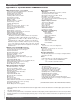
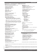
Specifications

58
Sabine Smart Spectrum
®
Wireless
© 2009 Sabine, Inc.
Appendix D: Dip Switch Settings
Front Panel Lock Status: LOCK 1 indicates all front panel controls are
locked to prevent intentional tampering, or accidental programming. LOCK
2 indicates a subset of controls are locked, allowing selected others to be
adjusted with software only. Default LOCK 2 setting locks out all functions
except FBX and Program Load. In addition, the LCD contrast control is not
locked in Lock 2.
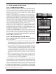
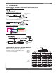
(Located on the receiver back panel)
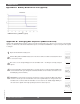
IMPORTANT: Dip Switches 1, 3, 4, & 8 must
always be in down position! The error message
to the right will display on the receiver if the #1
dip switch is not in the down position.
NOTE 1: LOCK 1 overrides LOCK 2.
NOTE 2: Down is the default position.
N
OTE 3: Lock settings are saved with the
Presets.
Networking: The first receiver con-
nected to the PC must have dip switch
#7 set to the down position (default).
All other receivers connected within a
network must have dip switch #7 set to
the up position.
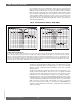
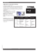
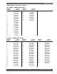
# SERIES DESCRIPTION UP STATUS DOWN STATUS
1 ALL (Always Down) Error OK
2 ALL FBX Filter Width 1/5 Octa
ve 1/10 Octave
3 a
LL (Always Down) Error OK
4 ND
only Digital Output External Word (Default) Internal
Clock Source Clock Input Clock Source
5 ALL
Lock 1 Lock Unlock
6 ALL Lock 2 Loc
k Unlock
7 ND
only Network Enable Networked No networking,
receivers or 1st receiver in
other than 1st. network.
8 ALL (Always Down) Error OK
DIP SWITCH STATUS CHART
Appendices