
Specifications


6
words, diversity is more important that coverage. If you mount the extension antennas in the ceiling, the
antennas metallic backplane must be orientated parallel to the floor and the antennas must not be blocked by
pillars, lights or similar obstructions. Aim the hole in the plastic cover toward the podium.
Do not daisy-chain extension antennas together in series. Receivers and the antenna distribution amp are
only designed to use one left and one right antenna.
Extension Antenna Cables: Use coax cable to connect the extension antennas to the receiver or to the ADA.
See the chart on the previous page for cable specifications. Use the SWATNC-N step-down cable to connect
thicker RG8 cables to the extension antenna.
The SWASS-EXT extension antennas add between 10 and 18dB signal strength to overcome cable loss. Bad
crimp connections are a common cause of dropouts. Check them carefully!
Keep the system away from electrical-noise sources (electric motors, refrigerators, arc welders, etc.). Place
the Antenna Distribution Amp at least 1.5 meters above floor level. Keep all transmitters at least 3 meters away
from a receiver antenna.
As a general precaution, keep 2.4 GHz cordless telephones, microwave ovens, WLAN antennas and 2.4 GHz
wireless video camera transmitters twice the distance from your Sabine wireless microphone system antennas
as that of your Sabine 2.4 GHz transmitters.
General Installation Cautions
1. Power Supply — Be sure to plug your unit into an appropriate power source.
2. Antenna Shorting — Be careful not to allow the antenna to come in contact with metal surfaces (antenna divider
case, other wires, cables, etc.).
3. Receiver to Antenna Distribution Amplifier cables — Keep these cables as short as possible. It is
recommended to use the cables supplied with your Antenna Distribution Amplifier.
4. Extension Antenna cables — For best results, use high quality coaxial cable with a 50 Ohm impedance.
Specifications will vary by cable manufacturer. See the chart for recommended cables on page 8. For best
results, use cable with minimal attenuation. The longer your cable, the more you will reduce the 100-meter range
between transmitter and receiver antenna. A well-placed pair of extension antennas will eliminate trouble spots
and generally improve overall performance of the wireless.
Common Sources of RF Interference
Since Marconi and others pioneered the first radio broadcasts, the radio spectrum has become increasingly
crowded with a huge diversity and variety of RF sources. The strength, frequency, location, and timing cycles of
these RF sources create a shifting pattern of interfering and overlapping frequencies and coverage patterns, which
can render the use of radio microphones a difficult and unpredictable business.
The typical sources of interference for conventional wireless mics can be high-powered broadcasters such as
radio stations and TV transmitters, or other short-range wireless devices, including multiple radio microphones
operating at the same location (either by design, or by coincidence), that operate in proximate (or harmonically
related) bands. Less commonly, interference may arise from spurious outputs emitted by electronic equipment
(notably computers, printers, or similar devices with digital clocks), faulty electrical equipment, neon signs, dim-
mers and lighting controllers, and so forth.
Many UHF and VHF mics are especially vulnerable because they share the RF spectrum with the very high-powered
transmitters for television. The coming conversion to digital and high-definition broadcast will increase the problems for
UHF and VHF.
The 2.4 to 2.4835 GHz frequency band is not only well above the fundamental (nominal) transmission frequen-
cies of such strong analog and digital broadcasts, but also high enough to escape interference problems occurring
at the strong first harmonic of even the highest digital television broadcast. The band is approved worldwide for a
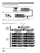
Antenna Distribution Amplifier Installation Cautions