TALEA TECHNICAL SERVICE MANUAL All parts of this document are property of Saeco International Group. All rights reserved. This document and relative information herein are provided without liability deriving from any errors or omissions. Furthermore, no part may be reproduced, used or collected with the exception of that authorised in writing or in accordance with a contractual clause. Issue August 2006 REV.
TALEA TECHNICAL SERVICE MANUAL (Rev 00 Aug.06): CONTENTS 1. 1.1 1.2 1.3 1.4 Introduction (rev.00) Documentation required Tools and equipment required Safety warnings Talea range 2. Technical data (rev.00) 2.1 Product technical data 2.2 Internal / external machine components 3. Summarised instructions (rev.00) 3.1 Client and programming menu (rev.00) 3.2 Maintenance and cleaning (rev.00) 4. Diagrams (rev.00) 4.1 Wiring diagram (rev.00) 4.2 Water circuit diagram (rev.00) 5. 5.1 5.2 5.3 5.
SECTION 1 INTRODUCTION REV.
1.1 Documentation required The following technical documentation is required for repairs: Instruction booklet for specific model. Technical documentation for specific model (diagrams, exploded drawings). 1.2 Tools and equipment required As well as the standard equipment, the tools listed below are required. 1 special screwdriver with Torx T10 tip. 1 digital thermometer with full 200°C scale. This must be suitable for measuring in liquids and on surfaces. 1 set of pliers for Oetiker clamps. 1 pincer.
1.
SECTION 2 TECHNICAL DATA REV.
2.1 Product technical data Power supply and output: Temperature control: Safety system: Coffee heat exchanger output: Stainless steel Motorized tank only on Talea Touch and Ring Plus.
2.
Talea Ring (Only for Ring Plus) (Motorized on Ring Plus only) TALEA Section 02 REV00 - August 06 3/4
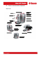
Internal components Heater Pump Static eliminator Turbine CPU Card Power board Coffee grinder Solenoid pilot Motorized tank stepper motor TALEA Section 02 REV00 - August 06 4/4
SECTION 3 BRIEF INSTRUCTIONS REV.
3.1 Client and programming menu Talea Touch The programming menu will open. Press “go to menu” Main menu Detailed beverage programming To set current time Show text 8:30 a Go to diagnostics Next page Beverage settings Machine settings Clock Maintenance settings Next Machine function programming Go back Exit After setting each of the following menus, press: - “Go back” to be returned to the previous screen and save any new settings. - “Previous settings” to reset previous values.
Talea Ring Plus To open programming menu. Use the touch-ring to select the type of beverage you want. Strong aroma Espresso coffee 08:33 To select milk-based beverage. MENU Confirm key. To select coffee aroma. Hot water key. Beverage settings To set beverage preparation parameters: press the MENU key and use the touch-ring to select “beverage settings”. At this point, you can: Exit the programming page.
3.2 Maintenance and cleaning STEPS A B C D E F Empty coffee grounds drawer. Empty drip tray. Clean water tank. Clean the coffee granule container. Clean casing. Clean and grease the brew group. H J K Descaling. Clean drip tray. Clean coffee circuit. As instructed. As necessary. Once a week. As necessary. As necessary Monthly or every 500 coffees. As instructed. Weekly. Weekly. Descaling.
SECTION 4 DIAGRAMS REV.
4.
Talea Ring Plus TALEA Section 04 REV00 - August 06 2/5
Talea Ring TALEA Section 04 REV00 - August 06 3/5
Talea Giro TALEA Section 04 REV00 - August 06 4/5
4.
SECTION 5 TROUBLESHOOTING REV.
5.1 Test functions Talea Touch 3 2 1 4 In the first three seconds after the appliance is switched on, you can enter test mode by pressing the keys in the sequence shown on the left. t.0 Software version Next CPU_V01.04.09 * * On entering test mode, the screen shown in the screenshot opens. Press the next key to move on to subsequent levels. * Level T1 – brew group At this level, brew group gearmotor and associated microswitches function is tested. t.
- Milk island present indicates the state of the milk island present microswitch. - Caraffe present indicates the state of the milk carafe present microswitch. - Pressing “valve” once will excite the solenoid valve. - Pressing “water pump” once will start the pump. - Pressing “valve” once will activate the solenoid valve. Level T4 – Grinder unit At this level, you can test coffee grinder function. t.
Level T7 – Coffee grounds drawer At this level, you can modify the current value of the number of coffee grounds (maximum of 13). t.7 - Dreg counter Next Max dreg counter = 13 Current dreg counter = 9 Value up Value down - max dreg counter - indicates the maximum number of coffee grounds that the drip tray can contain. - current dreg counter - indicates the current number of coffee grounds * Level T8 – Steam out At this level, you can drain the water circuit.. t.
Talea Ring and Ring Plus 3 1 2 4 When in test mode Switch the appliance on (double-pole switch on right side) and wait for the CA to finish initializing; then press and hold the illustrated menu key for 2 seconds until the string “Exit” appears on the screen. Press the capacitive keypad keys in the order shown on the left within the next two seconds. Exit MENU STEAM MENU WATER AROMA COFFEE The following string appears when you enter test mode: *Test* M0 12345 oo:mm:ss *Test* MO oo:mm:ss SWvx.xx.
Level M2 Gearmotor function is tested at this level. To move the gearmotor, the coffee grounds drawer and side door microswitches must be excited. The status of the microswitches listed below is shown at the right of the top line on the display: 1 2 3 6 7 Brew group presence microswitch excited. Brew group work position microswitch excited. Brew group home position microswitch excited. Side door closed microswitch excited. Coffee grounds drawer presence microswitch excited.
Level M4 At this level you can check water heater, relative ntc sensor and cup warmer function. - When you press the steam key, the ambient temperature (tt.t) is shown on the second line of the display in degrees centigrade. - When you press the water key, the state of the ntc sensor (open or short) on the water heater (open o short), or the water heater temperature in degrees centigrade are shown on the second line of the display.
TALEA GIRO Coffee key Press once to select a coffee. Press twice to select a double coffee. Stops coffee from being dispensed when pressed during dispensing. Water/steam key To select either water or steam. Press and hold for 6 seconds to “reset” descaling alarm. When off, indicates that the machine is ready to release steam. When on, indicates that the machine is ready to dispense water. Aroma key To select either a mild coffee, a medium coffee or a strong coffee.
Messages/Alarms Temperature ready LED Fixed on. Indicates “Coffee ready” or “Steam ready”. Temperature ready LED Slow blinking. The correct temperature has not been reached. Water/steam LED Off The appliance is in steam mode. Water/steam LED Fixed on. The appliance is in water mode. Aroma LED Fixed on. To set aroma. General alarms LED Fixed on. General alarms LED Slow blinking. General alarms LED Fast blinking. Fill water tank. Empty drip tray. Out of coffee (*) Door open.
POSITION POTENTIOMETER ACTION CHECK Solenoid pilot Press Coffee grinder Press Set aroma. (default: 90-100-110 pulses). Press Valve open. Brew group missing microswitch Drawer missing microswitch Door open microswitch. Coffee container cover microswitch Carafe present microswitch (with valve closed). Turbine sensor (during pump function) Water tank sensor Coffee grounds drawer lights up and stays on. blinks slowly. blinks slowly. blinks slowly. blinks slowly. lights up and stays on. blinks (turb.
POSITION POTENTIOMETER ACTION CHECK Pump Press Unit up. Press Set aroma. (default: 90-100-110 pulses). Press Unit microswitch up. + Steam key pressed. Valve open. blinks quickly. lights up and stays on. Brew group missing microswitch blinks slowly. Drawer missing microswitch blinks slowly. Door open microswitch. Coffee container cover microswitch blinks slowly. blinks slowly. Carafe present microswitch (with valve closed). lights up and stays on.
POSITION POTENTIOMETER ACTION Open valve and press Press Brew group missing microswitch Drawer missing microswitch Door open microswitch. Coffee container cover microswitch POSITION POTENTIOMETER CHECK Steamout procedure. While the procedure is underway (for a total of 30 seconds), the following LEDs light up alternately one after the other in a clockwise direction light up and each time the key is pressed, the number of pulses for AVERAGE AROMA is reduced by 5 pulses to a minimum of 60 pulses.
DIP SWITCH ON 1 ON 2 3 CONFIGURATION ODEA GO DEFAULT DATA MILD STRENGTH 54 59 63 68 72 77 81 86 90 95 99 104 108 113 117 122 126 131 135 1 ON 2 3 CONFIGURATION ODEA GIRO AROMA PULSES MEDIUM STRENGTH 60 65 70 75 80 85 90 95 100 105 110 115 120 125 130 135 140 145 150 1 2 3 CONFIGURATION TALEA GIRO STRONG STRENGTH 66 71 77 82 88 93 99 104 110 115 121 126 132 137 143 148 154 159 165 TALEA Section 05 REV00 - August 06 12/17
5.2 Diagnostics function Talea Ring Plus 2 1 4 3 When in diagnostics mode Switch the appliance on (double-pole switch on right side) and wait for the CA to finish initializing; then press and hold the menu key for 2 seconds until the string “Exit” appears on the screen. Press the capacitive keypad keys in the order shown on the left within the next two seconds.
Level M3 : Error Log 3.1 Errors List The following are shown at this level: -) -) The last 20 errors involving the CA The date the error occurred. The error map is shown below: Code Brief description Description COFFEE GRINDER ERRORS Coffee grinder blocked. The coffee grinder won’t turn: there may be something obstructing the grinders or beverage signal has not been read correctly by the Hall probe in the coffee grinder.
Level M4 : Products Settings The parameters for each different beverage are shown at this level; these parameters can be modified by opening each item using the coffee key and selecting with the touch-ring. 4.1 Espresso Settings: 4.1.1 Product Qty. (imp.) 4.1.2 Aroma 4.1.3 Prebrewing 4.1.4 Temperature Number of water pulses. Displays coffee grinder pulses in 60-150 pulse range. 0: pre-ground (0 pulses); 1: mild (- 10% medium); 2: medium; 3: strong (+10% medium). Prebrewing 1: enabled; 0: disabled; 2: long.
REV00 - August 06 All models Primea All models All models All models Primea Primea Primea All models Primea All models All models All models All models All models All models 01 02 03 04 05 06 08 09 10-11 12-13 14-15 16 17 18 19 20 Heater temperatures out of control. Steam heater sensors shorted or in open circuit. Cup lift error. No zero crossing. Clock error. Memory error. The two stroke end position microswitches are activated at the same time.
5.4 Problems, causes, remedies HELP MESSAGES DISPLAYED HOW TO RESET MESSAGE Turn the appliance off and on to solve the problem. Switch off and after 30 sec. turn on the appliance to restore normal operating conditions. Call the Service Centre. Problem requiring assistance of Service Centre. Insert drip tray. Insert drip tray. Close coffee granule container cover. Close the coffee granule container to enable delivery of any beverage. Insert ground coffee.
SECTION 6 OPERATING LOGIC REV.
6.1 Reset coffee grounds drawer. The “empty coffee grounds drawer” message is signalled by a “coffee” beverages counter controlled by the appliance electronics. The counter is cleared “empty coffee grounds drawer” reset message: 1. After 13 coffees, if the grounds drawer is removed for more than 5 seconds. 2. Each time the grounds drawer is removed for more than 5 seconds when an “empty coffee grounds drawer” alarm has been generated (it is assumed that the grounds drawer has been emptied). N.
6.3 Motorized tank The movement of the motorized tank is mechanical by means of a stepper motor (1) in 24V DC, controlled by two capacitive pushbuttons (2) located at the front of the tank. The two microswitches (3) are for the limit switch, and operation can be checked in test mode (see section 5.1).
6.4 Aqua Prima Operating logic with “AQUA PRIMA” filter. When use of the “aqua prima” filter is selected on the user menu or via the control panel, the system water count logic is as follows: If the “aqua prima” function is enabled the electronics perform a pulse count of the turbine, recording one pulse every 2 revolutions. If the “aqua prima” function is disabled, the electronics perform a pulse count of the turbine, recording one pulse every revolution.
6.5 SBS Valve Beverage dispensing The SBS brewing system valve (see Fig. 2) controllable via the knob, enables variation (increasing or decreasing according to the position of the knob) of the water flow rate for brewing. This adjusts the coffee brewing time (extraction time) and consequently the intensity of taste, keeping the cream quality constant. Function With the SBS valve in the open position, coffee is accumulated in the membrane valve due to a low back-pressure of the SBS valve.
SBS valve operation check To ensure correct operation of the valve SBS a long coffee should be made, and during preparation of the latter, check the difference in dispensing speed between the maximum and minimum positions. The difference in dispensing speed is approx. 2.5 times greater (and therefore VERY obvious!!).
6.6 Solenoid pilot Needle Drain Brew group valve (3 - 5 bars) Brew group drain valve Solenoid pilot function: 1. Brew group drain: before the group is lowered, the solenoid pilot opens briefly creating a depression that in turn opens the valve in the opposite direction from dispensing, allowing any water left in the group to be drained and keeping the pad dry. 2. Coffee ready after steam: when a coffee or water are selected, the solenoid pilot opens the drain valve to lower pressure in the heater.
6.7 Milk Island Electrical connection to appliance. Button to attach/release Milk Island from appliance. Water pipe connected to appliance for steam inlet. Steam outfeed Anchor pin between Milk Island and appliance. Carafe present LED Unscrew bolts indicated to dissassemble. 1 5 2 1 Cappucinatore cover. 3 2 Cappucinatore valve cover. 4 3 Vernay valve. 4 6 7 Cappucinatore valve cover insert. 5 Cappucinatore body. 6 Carafe handle. 8 7 Carafe milk suction pipe. 8 Carafe steamout pipe.
SECTION 7 COMPONENT ASSEMBLY AND DISASSEMBLY REV.
7.1 Top cover Remove the coffee container cover, loosen the indicated screws and pull off the steam knob. To remove the coffee brew unit cover, follow the steps in a clockwise direction, remove the SBS knob, loosen the middle screw, take off the knob support, and loosen the indicated screws. Pull out coffee container cover sensor. Raise the cover from the back and then pull on the front part as shown in the photo. Unfasten the PTC connection from the cup warmer.
7.2 Right and left side casing Loosen the screw as shown. To remove the right side, loosen the screws as indicated. To remove the left side, loosen the screws as indicated. To take the left-side off, release the small clamp and pull out the wire mesh pipe connecting the steam pipe to the valve, removing the metal band as shown. 1 2 Split the two sides of the casing (see Fig..1). Press from the bottom (see Fig.2). Release and take it off from the side and at the bottom (see Fig.
7.3 Electronics CPU card 2 1 3 Fig.1 Loosen the screws as indicated and turn the front piece upwards to get to the card. Fig.2 Take off the small clamp. Fig.3 Disconnect all connectors and loosen the screws as indicated. Power board Remove the small clamps, disconnect all connectors and loosen the screws indicated.
7.4 Gearmotor A B Remove the safety guard (A) by loosening the screws as indicated. Loosen the two screws indicated and remove the heater pin. When refitting it, be careful with the two oil-rings shown in the smaller picture. The following are fitted inside the compartment protected by the guard: - Electric motor (A) with gears (B) and (C) for transmission and timing of the brew group. - The drip tray presence reed switch sensor (D). - Brew group presence microswitch (E).
7.5 Pump 1 2 Take the pump out from the rubber support guides. Pull out the adapter. TALEA Section 07 REV00 - August 06 Withdraw the faston connectors as indicated. Take off the oetiker clamp as indicated and pull out the reinforced flexible hose.
7.6 Heater and solenoid pilot unit Loosen the screws as indicated. A B C Loosen the screws on the relief valve assembly. Take off the oetiker clamp A, pull out the reinforced flexible hose, loosen screw B and withdraw the drain pipe C from the solenoid pilot. A Heater Unhook the teeth anchoring to the body and lift the heater and solenoid pilot. Solenoid pilot.
7. 7 OETIKER clamp assembly and disassembly Heater clamps 1 HEATER Figure (1) shows the assembly position of the clamp on the heater connector. Solenoid pilot 2 SOLENOID PILOT Figure (2) shows the assembly position of the clamp on the plastic solenoid pilot connectors. A Use suitable pliers to tighten the clamp. Ensure correct tightening (A) and positioning as shown in illustrations (1) / (2).
7.8 Coffee grinder A Loosen the screws on the cover and lift it off, being careful to withdraw damper A. Unclamp and remove the connector inserted in the card. When refitting the motor assembly, be careful to reinsert the spring.
7.9 Coffee grinder setting, assembly and disassembly To remove the upper grinder support, use a wrench, turning it clockwise to release the grinder support from the bayonet coupling. To remove the grinder, rotate anticlockwise until it detaches from the bayonet coupling. On the lower grinder, keep the increment pin as indicated locked in position and proceed as shown in the figure above. When refitting the upper grinder support, take care to reposition the mark as shown in the picture.
7.10 Grinder adjustment during servicing To adjust the coffee grinder (in addition to user-permitted adjustments of “C” with the grinding adjustment tool “A”), remove the coffee granule container and turn adjustment insert “B” to widen or tighten grinding. This insert can be repositioned to move interval “C”. Be very careful not to separate the grinders from their supports. C B Loosen the screw on the coffee container. - + To vary the grinding setting, tighten or loosen with wrench “A” supplied.
7.11 Motorized drip tray Loosen the screws as indicated. Pull the motorized tray towards you. To reach the capacitive sensors, loosen the two screws to remove the safety guard under the drip tray. Remove electrical connections (G) as indicated. Disassembling the motorized tank stepper motor Loosen the two screws to release the electric motor with worm gear TALEA Section 07 REV00 - August 06 To withdraw the stop (A) use pliers to grip the tabs securing the lifting system to the base and pull outwards.
SECTION 8 SERVICE SCHEDULE REV.
8.1 Routine maintenance check list S= Replacement R= Service P= Cleaning D= Descaling C= Inspection *= Number of beverages dispensed Item 10,000* Reason 5,000* Task Service Parts C C C Dirty, damaged. See documentation (exp. drawing). S S C C C C S S D D D D S S D D D D Wear Dirty, Dirty, Dirty, Dirty, Dirty, See documentation (exp. drawing). See documentation (exp. drawing). See documentation (exp. drawing). See documentation (exp. drawing).