Professional Workstation AP500 Maintenance and Service Guide Second Edition (March 1999) Part Number 338534-002 Spares Part Number 338561-001 Compaq Computer Corporation
Notice The information in this publication is subject to change without notice. COMPAQ COMPUTER CORPORATION SHALL NOT BE LIABLE FOR TECHNICAL OR EDITORIAL ERRORS OR OMISSIONS CONTAINED HEREIN, NOR FOR INCIDENTAL OR CONSEQUENTIAL DAMAGES RESULTING FROM THE FURNISHING, PERFORMANCE, OR USE OF THIS MATERIAL.
iii Contents About This Guide Text Conventions.......................................................................................................................vii Symbols in Text................................................................................................................ ........viii Symbols on Equipment........................................................................................................... ..viii Where to Go for Additional Help ..................................
iv Removal and Replacement Procedures continued Mass Storage Devices.............................................................................................................3-21 Drive Positions ................................................................................................................3-21 Hardware Screws.............................................................................................................3-23 CD-ROM Drive or DVD-ROM Drive......................................
v Diagnostic Tools continued Compaq Setup and Diagnostics Utilities.................................................................................4-19 Accessing the Compaq Utilities Menu ............................................................................4-19 Creating a Diagnostics Diskette.......................................................................................4-20 Computer Setup........................................................................................................
vi Chapter 6 Jumper and Switch Information Battery Jumpers ........................................................................................................................6-2 Switch Settings .........................................................................................................................6-3 Hard Drives ..............................................................................................................................6-4 32X Max CD-ROM Drive (IDE)...................
vii About This Guide This guide is designed to be used as step-by-step instructions for installation, and as a reference for operation, troubleshooting, and future upgrades. WARNING: Only authorized technicians trained by Compaq should attempt to repair this equipment. All troubleshooting and repair procedures are detailed to allow only subassembly/module level repair.
viii Symbols in Text These symbols may be found in the text of this guide. They have the following meanings. ! WARNING: Indicates that failure to follow directions in the warning could result in bodily harm or loss of life. CAUTION: Indicates that failure to follow directions could result in damage to equipment or loss of information. IMPORTANT: Presents clarifying information or specific instructions. NOTE: Presents commentary, sidelights, or interesting points of information.
ix Where to Go for Additional Help Major sources of additional information are listed below. Other Information Sources In addition to this guide, the following information sources are available: ■ User Documentation ■ Compaq Service Quick Reference Guide ■ Service Training Guides ■ Compaq Service Advisories and Bulletins ■ Compaq QuickFind ■ Compaq Insight Manager ■ Compaq Download Facility: Call 1-281-518-1418.
1-1 Chapter 1 Illustrated Parts Catalog This chapter provides an illustrated parts breakdown and a reference for spare parts for the Compaq Professional Workstation AP500. Mechanical Parts 49 24 11 100 6 12 9 100 2 10 4 98 1 Figure 1-1.
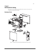
1-2 Illustrated Parts Catalog System Components 87 52 98 32 23 74 7 13 50 3 51 5 19 20 44 45 14 22 33 26 11 66 42 8 16 17 Figure 1-2.
1-3 Spares Parts List Parts or components marked with an asterisk (*) are not illustrated.
1-4 Illustrated Parts Catalog Compaq Professional Workstation AP500 Spares Parts List Continued Reference Description Spares Part # 22 External Battery 160274-001 23 Expansion Board Slot Cover 141081-001 24 Power Switch and LEDs with Cable 329270-001 25 32-MB Memory Module (Registered 100-MHz SDRAM) 317747-001* 26 64-MB Memory Module (Registered 100-MHz SDRAM) 317745-001 27 128-MB Memory Module (Registered 100-MHz SDRAM) 317756-001* 28 256-MB Memory Module (Registered 100-MHz SDRAM)
1-5 Compaq Professional Workstation AP500 Spares Parts List Continued Reference Description Spares Part # 47 4/8-GB SLR Drive 340591-001* 48 Hard Drive Mounting Bracket (Bays 5 and 6) 243231-001* 49 Fan and Cable for >7200 rpm Hard Drives Installed in Bay 5 or 6 329266-001 50 Miscellaneous Signal Cable Kit (CD-ROM Drive, HD, Diskette, Audio) 327649-001 51 SCSI cable, wide 338546-001 52 Wide Ultra2 SCSI cable 402222-001 53 SCSI adapter, 50- to 68-Pin (internal) 189638-001* CABLE KITS
1-6 Illustrated Parts Catalog Compaq Professional Workstation AP500 Spares Parts List Continued Reference Description Spares Part # GRAPHICS 66 GLoria Synergy+ Graphics Controller 4-MB (AGP) 327599-001 67 GLoria Synergy+ 4-MB Memory Upgrade 327600-001* 68 GLoria Synergy+ 8 MB (PCI) Graphics Controller 298796-001* 69 PowerStorm 300 Graphics Controller (AGP) 338539-001* 70 Matrox Millennium G200 Graphics Controller 294409-001* 71 Matrox Millennium G200 8-MB Memory Upgrade 386047-001* 72
1-7 Compaq Professional Workstation AP500 Spares Parts List Continued Reference Description Spares Part # SOFTWARE 89 Magellan Driver CD 297863-001* 90 Spaceball Driver CD 298033-001* 91 Microsoft Windows NT Workstation 4.
2-1 Chapter 2 Service Preliminaries This chapter identifies the following service considerations: ■ Preliminary warnings and cautions ■ Electrostatic discharge information ■ Equipment symbols ■ Tools and software requirements ■ Warranty information IMPORTANT: Adherence to the procedures and precautions described in this chapter is essential for proper service.
2-2 Service Preliminaries Preliminary Warnings and Cautions The following should be noted when operating or servicing the Compaq Professional Workstation AP500: WARNING: To reduce the risk of electric shock or damage to the equipment: ■ Disconnect power from the system by unplugging all power cords from either the electrical outlet or the Compaq Professional Workstation AP500. ■ Do not disable the power cord grounding plug. The ground plug is an important safety feature.
2-3 Electrostatic Discharge Information A discharge of static electricity can damage static-sensitive devices or micro-circuitry. Proper packaging and grounding techniques are necessary precautions to prevent damage. To prevent electrostatic damage, observe the following precautions: ■ Transport products in static-safe containers (conductive tubes, bags, or boxes). ■ Keep electrostatic-sensitive parts in their containers until they arrive at static-free stations.
2-4 Service Preliminaries Tools and Software Requirements To service the workstation, you might need: ■ Torx T-10 screwdriver ■ Torx T-15 screwdriver ■ Flat-blade screwdriver ■ Compaq Setup and Diagnostics Utility IMPORTANT: Prior to servicing the workstation, be sure the drivers from the latest Compaq Workstation SSD for Windows NT are installed. See Chapter 4 for installation procedures.
3-1 Chapter 3 Removal and Replacement Procedures This chapter provides subassembly/module-level removal and replacement procedures for the Compaq Professional Workstation AP500. After completing all necessary removal and replacement procedures, run the Compaq Setup and Diagnostics program to verify that all components are operating properly. Serial Number Provide the computer serial number to Compaq whenever you request information or order spare parts.
3-2 Removal and Replacement Procedures Service Preparations CAUTION: The power supply in the Compaq Professional Workstation AP500 has an auxiliary power section. This section is always active as long as the unit is plugged into a live AC outlet. Be sure to turn off the switch and unplug the power cord before performing any service work. CAUTION: Electrostatic discharge can damage electronic components. Be sure you are properly grounded before beginning any installation procedure.
3-3 Cable Lock The workstation comes standard with a cable lock provision for attaching a padlock and/or cable lock. If installed, the locks must be removed before accessing internal components. To remove the lock: 1. Unlock and remove the cable lock and/or the padlock 1. 2. Remove the security bracket (plate) seated over the cable lock bracket 2. 3. Unfasten the retaining screw to release the cable lock bracket 3. 1 3 2 Figure 3-2.
3-4 Removal and Replacement Procedures Workstation Feet NOTE: Not all procedures in this chapter require the removal of the workstation feet. Be sure to thoroughly read each removal and replacement procedure before attempting to access the workstation’s internal components. To remove the workstation feet: 1. Perform the service preparations shown on page 3-2, then lay the workstation on its side. 2. Remove the screws that secure the feet. 3. Remove the feet. Figure 3-3.
3-5 Side Access Panel CAUTION: Do not operate the workstation with the side access panel removed. The panel is an integral part of the cooling system; removing it while the system is operating may adversely affect data integrity. To remove the side access panel: 1. Perform the service preparations shown on page 3-2. 2. Loosen the four rear panel thumbscrews, then slide the side access off. Figure 3-4.
3-6 Removal and Replacement Procedures Front Bezel To remove the front bezel: 1. Perform the service preparations shown on page 3-2. 2. Remove the side access panel. 3. Push the front bezel release latches 1 and remove the bezel 2. T COMPAC 1 2 Figure 3-5. Removing the front bezel To replace the front bezel: 1. Line up the hinges and release latches with the appropriate slots on the front of the chassis. 2. Press the bezel in to secure the release latches.
3-7 Blank Drive Bezel To remove a blank drive bezel: 1. Perform the service preparations shown on page 3-2. 2. Remove the following components: 3. ❏ Side access panel ❏ Front bezel Remove the screws that secure the blank drive bezel to the front bezel. Figure 3-6. Removing a blank drive bezel To replace a blank drive bezel, reverse the above procedure.
3-8 Removal and Replacement Procedures EMI/Cooling Shield An EMI/cooling shield covers bays 5 and 6 to provide proper cooling and EMI protection. To remove an EMI/cooling shield: 1. Perform the service preparations shown on page 3-2. 2. Remove the following components: ❏ Side access panel ❏ Front bezel 3. Remove the two screws that connect the EMI/cooling shield to the drive cage. 4. Remove the EMI/cooling shield from the drive slot. ACT COMP Figure 3-7.
3-9 Speaker To remove the speaker: 1. Perform the service preparations shown on page 3-2. 2. Remove the side access panel. 3. Unplug the speaker connector from the system board 1, and remove the cable from the clip. 4. Remove the four T-15 screws securing the front of the speaker to the chassis 2. 5. Remove the speaker from the workstation by sliding it back, then lifting it up and out of the chassis 3. 1 2 3 1 Figure 3-8.
3-10 Removal and Replacement Procedures I/O Bracket Assembly The I/O bracket assembly (expansion board assembly) contains a backplane board (also called a riser card), card guide, and any expansion boards. To remove the I/O bracket assembly: 1. Perform the service preparations shown on page 3-2, then lay the workstation on its side. 2.
3-11 Replacing the I/O Bracket Assembly To replace the I/O bracket assembly (expansion board assembly), follow these steps: 1. Grasp the assembly and insert it into the chassis and connector on the system board. Press firmly on the I/O bracket assembly, where the backplane is connected to the system board. 2. Connect the power cord to the grounded AC outlet and to the workstation. DO NOT turn on the power switch. 3. Check if the power LED is a steady amber color.
3-12 Removal and Replacement Procedures Expansion Boards This section discusses removal and replacement procedures for PCI or ISA expansion boards and the Accelerated Graphics Port (AGP) graphics controller. NOTE: The following instructions also apply to installing and removing graphics controllers. For information about the installed graphics controller, refer to the appropriate guide on the SmartStart for Workstations CD under X:/DOCS/GRAPHICS, where X is the CD-ROM or DVD-ROM drive on your machine.
3-13 Table 3-1 PCI/ISA Slots Reference Description 1 PCI/ISA shared expansion slot* 2 PCI expansion slot 3 PCI expansion slot 4 PCI expansion slot 5 ISA slot *Cannot be used simultaneously NOTE: PCI=Peripheral Component Interconnect ISA=Industry Standard Architecture Compaq Professional Workstation AP500 Maintenance and Service Guide
3-14 Removal and Replacement Procedures Removing a PCI or ISA Expansion Board NOTE: The following instructions also apply to installing and removing graphics controllers. For information about the installed graphics controller, refer to the appropriate guide on the SmartStart for Workstations CD under X:\DOCS\GRAPHICS, where X is the CD-ROM or DVD-ROM drive on your machine. To remove a PCI or ISA expansion board: 1. Perform the service preparations shown on page 3-2, then lay the workstation on its side.
3-15 Removing a Symbios Wide Ultra2 PCI SCSI Controller NOTE: For best performance, do not mix Wide-Ultra and Wide Ultra2 SCSI hard drives on the same SCSI cable or the same channel. To remove a Wide Ultra2 SCSI Controller: 1. Perform the service preparations shown on page 3-2, then lay the workstation on its side. 2. Remove the following components: ❏ Workstation feet ❏ Side access panel 3. Remove the I/O bracket assembly. 4. Disconnect the SCSI cable from the controller. 5.
3-16 Removal and Replacement Procedures Removing the Accelerated Graphics Port (AGP) Graphics Controller The Compaq Professional Workstation AP500 comes equipped with an AGP expansion slot on the system board. The following illustration identifies the physical location of the AGP graphics controller expansion slot.
3-17 Removing the Card Guide To remove the card guide: 1. Perform the service preparations shown on page 3-2, then lay the workstation on its side. 2. Remove the following components: ❏ Workstation feet ❏ Side access panel ❏ I/O bracket assembly ❏ Full-length expansion boards, if installed 3. Using a blunt tool, press inward on the two center tabs on the card guide. 4. Gently pull the card guide out. Figure 3-13. Removing the card guide To replace the card guide, reverse the above procedure.
3-18 Removal and Replacement Procedures Removing the Backplane Board The backplane board (also called the riser card) is attached to the I/O bracket assembly. The backplane board contains the expansion slots described and shown in the “Expansion Boards” section in this chapter. To remove the backplane board: 1. Perform the service preparations shown on page 3-2, then lay the workstation on its side. 2.
3-19 System Fan To remove the system fan: 1. Perform the service preparations shown on page 3-2, then lay the workstation on its side. 2. Remove the following components: ❏ Workstation feet ❏ Side access panel 3. Disconnect the fan cable from the system board 1. 4. Remove the two screws at the top of the fan 2, then pull back and slide up 3. NOTE: If the system board has not been removed, slide it out a few inches before removing the system fan. 1 2 3 2 Figure 3-15.
3-20 Removal and Replacement Procedures 5. Pull the rubber isolators through the bracket 1, then remove the fan from the bracket 2. 1 2 Figure 3-16. Removing the fan from the bracket To replace the system fan, reverse the above procedure.
3-21 Mass Storage Devices This section discusses removal and replacement procedures for the mass storage devices supported on the Compaq Professional Workstation AP500. Drive Positions The Compaq Professional Workstation AP500 can house up to seven mass storage devices. All models ship with a CD-ROM drive installed in Bay 4 and a diskette drive installed in Bay 7. The following illustration identifies the physical drive locations. See the corresponding table for a description of the drive bay components.
3-22 Removal and Replacement Procedures Table 3-2 Drive Positions Reference Component Description 1 Bay 1 Part of the removable hard drive cage. A 3.5-inch, third-height bay that supports a 1.0-inch hard drive or a 1.6-inch hard drive. 2 Bay 2 Part of the removable hard drive cage. A 3.5-inch, third-height bay that supports a 1.0-inch hard drive. Bay 2 is not available when a 1.6-inch hard drive is installed in Bay 1 or Bay 3. 3 Bay 3 Part of the removable hard drive cage. A 3.
3-23 Hardware Screws A total of 17 extra hardware screws are provided on the side of the air plenum. The top group of eight screws 1 is for installing hard drives in the removable hard drive cage. The bottom group of nine screws 2 is for installing removable media storage devices in the front drive bays. 1 2 Figure 3-18.
3-24 Removal and Replacement Procedures CD-ROM Drive or DVD-ROM Drive To remove the CD-ROM drive or DVD-ROM drive: 1. Perform the service preparations shown on page 3-2. 2. Remove the following components: ❏ Side access panel ❏ Front bezel 3. Remove the retaining screws 1 and slide the drive 2 halfway out. 4. Disconnect the audio, data, and power cables 3 from the back of the drive. 1 CT COMPA 3 2 Figure 3-19.
3-25 5. Pull the drive completely out of the drive cage. CT COMPA Figure 3-20. Removing the CD-ROM drive or DVD-ROM drive To replace the drive, reverse the above procedure. CAUTION: Use only 3/16-inch or 5 mm long screws. Using longer screws can damage the internal components of the drive. CAUTION: When servicing the workstation, be sure cables are placed in their proper locations during the reassembly process. Improper cable placement can damage the computer.
3-26 Removal and Replacement Procedures Diskette Drive IMPORTANT: Before removing the diskette drive, be sure there is no diskette in the drive. To remove the diskette drive: 1. Perform the service preparations shown on page 3-2. 2. Remove the following components: 3. ❏ Side access panel ❏ Front bezel Disconnect the cables from the back of the diskette drive. Figure 3-21. Disconnecting the cables from the back of the diskette drive 4. Remove the diskette drive retaining screws.
3-27 5. Pull the diskette drive straight out. ACT COMP Figure 3-22. Removing the diskette drive To replace the diskette drive, reverse the above procedure. CAUTION: Use only 3/16-inch or 5 mm long screws. Using longer screws can damage the internal components of the drive. CAUTION: When servicing the workstation, be sure cables are placed in their proper locations during the reassembly process. Improper cable placement can damage the computer.
3-28 Removal and Replacement Procedures Removing a 7200 rpm Hard Drive from Bays 5 or 6 Drive bays 5 and 6 can be configured with either a 1.0-inch or a 1.6-inch, 7200 rpm hard drive. Other than using different screw holes, the removal of both drives a basically the same. To remove a 7200 rpm hard drive: 1. Perform the service preparations shown on page 3-2. 2. Remove the following components: 3. ❏ Side access panel ❏ Front bezel Disconnect the signal and power cables. Figure 3-23.
3-29 4. Remove the EMI/cooling shield. ACT COMP Figure 3-24. Removing the EMI/cooling shield 5. Pull the hard drive straight out. COMPACT Figure 3-25.
3-30 Removal and Replacement Procedures 6. Remove the retaining screws and lift the hard drive from the bracket. Figure 3-26. Removing a hard drive from the hard drive bracket To reinsert a hard drive in Bays 5 or 6, reverse the above procedure. CAUTION: Use only 3/16-inch or 5 mm long screws. Using longer screws can damage the internal components of the drive. CAUTION: When servicing the workstation, be sure cables are placed in their proper locations during the reassembly process.
3-31 Removing a 10,000-rpm Hard Drive from Bays 5 or 6 Drive bays 5 and 6 can be configured with a 10,000 rpm hard drive. The removal of the drive is basically the same as removing a 7200 rpm hard drive except you will be also be removing a cooling fan. : To remove a 10,000-rpm hard drive: 1. Perform the service preparations shown on page 3-2. 2. Remove the following components: 3. ❏ Side access panel ❏ Front bezel Disconnect the signal and power cables. Figure 3-27.
3-32 Removal and Replacement Procedures 4. Disconnect the fan power cable. Figure 3-28. Disconnecting the fan power cable 5. Remove the retaining screws securing the fan. NOTE: The screws that secure the fan also secure the hard drive. Figure 3-29.
3-33 6. Remove the EMI/cooling shield. ACT COMP Figure 3-30. Removing the EMI/cooling shield 7. Pull the hard drive straight out. COMPACT Figure 3-31.
3-34 Removal and Replacement Procedures 8. Remove the retaining screws and lift the hard drive from the bracket. Figure 3-32. Removing a hard drive from the hard drive bracket To reinstall a hard drive in Bays 5 or 6, reverse the above procedure. CAUTION: Use only 3/16-inch or 5 mm long screws. Using longer screws can damage the internal components of the drive. CAUTION: When servicing the workstation, be sure cables are placed in their proper locations during the reassembly process.
3-35 Removing the Fan from a Hard Drive Installed in Bays 5 or 6 NOTE: This section only applies if there is a fan installed over Bays 5 and 6. The fan is required only in high-altitude environments or when a hard drive faster than 7200 rpm is installed in Bay 5 or 6. To remove the fan: 1. Perform the service preparations shown on page 3-2. 2. Remove the side access panel. 3. Disconnect the power cable. Figure 3-33.
3-36 Removal and Replacement Procedures 4. Remove the screws that hold the fan in place and remove the fan. NOTE: The screws also secure the hard drive in that bay and must be replaced. DO NOT remove the screws from the CD-ROM drive. They are not used to install the fan. Figure 3-34. Removing the fan To replace the fan, reverse the above procedure.
3-37 Removing a Hard Drive from the Removable Hard Drive Cage The removable hard drive cage supports up to three 1.0-inch hard drives or two 1.6-inch hard drives. Other than using different screw holes, the removal and replacement for both drives is basically the same. To remove a hard drive in the removable hard drive cage: 1. Perform the service preparations shown on page 3-2, then lay the workstation on its side. 2. Remove the following components: 3.
3-38 Removal and Replacement Procedures 4. Pull back the power supply air baffle 1. 5. Loosen the two thumbscrews 2 and slide the removable hard drive cage out 3. 2 3 1 Figure 3-36. Removing the removable hard drive cage 6. Remove the four screws that secure the hard drive to the removable hard drive cage and pull the hard drive straight out. Figure 3-37.
3-39 Installing a Hard Drive in the Removable Hard Drive Cage To install a hard drive in the removable hard drive cage: 1. Perform the service preparations shown on page 3-2, then lay the workstation on its side. 2. Remove the following components: 3. ❏ Workstation feet ❏ Side access panel ❏ Removable hard drive cage Remove the hard drive screws (top group of screws) from the side of the air plenum located at the front of the workstation. 4 3 2 1 Figure 3-38.
3-40 Removal and Replacement Procedures Figure 3-39. Inserting a hard drive in the removable hard drive cage 4 2 1 3 Figure 3-40. Reinstalling a removable hard drive cage 5. Pull back the air baffle 1. 6. Slide the hard drive cage 2 into place. 7. Align the tabs 3 on the bottom of the cage with the workstation chassis. 8. Tighten the thumbscrews 4. 9. Connect the signal and power cables to the hard drive. 10. Reassemble the workstation.
3-41 SCSI Cables and Guidelines All workstation models use three areas for connecting mass storage SCSI devices: internally with hard drive in the removable hard drive cage, internally with storage devices in the front panel drive bays, and externally with external storage devices. The workstation has an integrated Wide-Ultra SCSI controller that has one internal connector on the system board and one external connector on the rear panel.
3-42 Removal and Replacement Procedures SCSI Guidelines for Installing SCSI Devices ■ If you are installing a narrow SCSI device, you will need to attach a 68- to 50-pin SCSI adapter to the narrow SCSI device. ■ A maximum of seven SCSI devices may be installed on the integrated Wide-Ultra SCSI controller. ■ A unique SCSI ID (0-6 and 8-15) must be set for each SCSI device installed.
3-43 System Board Assembly The system board assembly contains the DIMMs, Pentium II or Pentium III processor/heat sink, Processor Power Module(s), system board with tray, the AGP Graphics Controller, and the external battery, if installed. Each of these components is spared separately. The components on the system board are illustrated in Figure 3-43. See Table 3-4 for component names. CAUTION: Static electricity can damage the electronic components of the workstation.
3-44 Removal and Replacement Procedures To install a new system board with tray and cage: 1. Remove the following components from the system board with tray: ❏ DIMMs ❏ Processor(s) ❏ Processor power module(s) ❏ External battery (if installed) 2. Install the components on the new system board with tray. Before reinstalling the DIMMs, see “Important Guidelines for DIMM Installation” earlier in this chapter. 3. Slide the new system board with tray into the chassis. 4.
3-45 System Board Components 1 2 3 4 5 6 7 8 9 10 11 18 12 13 14 17 15 16 Figure 3-43.
3-46 Removal and Replacement Procedures Dual Inline Memory Modules (DIMMs) The Compaq Professional Workstation AP500 has four DIMM slots on the system board to support up to a maximum of 1 GB. See the following illustration for the physical location of the DIMM sockets. DIMM 4 DIMM 3 DIMM 2 DIMM 1 Figure 3-44. Overview of DIMM sockets NOTE: DIMMs do not need to be installed in pairs, and can be installed in any of the available DIMM sockets. The DIMM sockets are numbered in sequence from 1-4.
3-47 Removing a DIMM CAUTION: When handling a DIMM, be careful not to touch any of the contacts. Doing so may damage the DIMM. CAUTION: Static electricity can damage the electronic components of the workstation or optional boards. Before beginning these procedures, ensure that you are properly grounded. See “Electrostatic Discharge Information” in Chapter 2. To remove a DIMM: 1. Perform the service preparations shown on page 3-2, then lay the workstation on its side. 2.
3-48 Removal and Replacement Procedures Processor and Heatsink Assembly WARNING: To reduce the risk of personal injury from hot surfaces, allow the internal system components to cool before touching. To remove the processor and heatsink assembly: 1. Perform the service preparations shown on page 3-2, then lay the workstation on its side. 2. Remove the following components: 3.
3-49 Processor Power Module CAUTION: Static electricity can damage the electronic components of the workstation. Before beginning these procedures, make sure you are properly grounded. See “Electrostatic Discharge Information” in Chapter 2. The processor power module (voltage regulator module) is located on the system board. To remove the processor power module: 1. Perform the service preparations shown on page 3-2, then lay the workstation on its side. 2.
3-50 Removal and Replacement Procedures Primary Processor Power Module Cable Insulator A cable insulator reduces damage to cables routed over the power module. If you are replacing the primary processor module, you must first remove the cable insulator from the module and place it on the new power processor module. To remove the cable insulator: 1. Perform the service preparations shown on page 3-2, then lay the workstation on its side. 2.
3-51 External Battery The real-time clock battery that came with the workstation is permanently installed on the system board. If the original battery becomes inoperative, you must install a replacement battery. Before attempting to install the replacement battery, read the following section. Running Computer Setup Computer Setup automatically detects and configures most Compaq components, including Compaq hard drives.
3-52 Removal and Replacement Procedures Installing the Battery CAUTION: Static electricity can damage the electronic components of the workstation. Before beginning these procedures, make sure you are properly grounded. See “Electrostatic Discharge Information” in Chapter 2 for more information. To install an external real-time clock battery: 1. Perform the service preparations shown on page 3-2, then lay the workstation on its side. 2.
3-53 5. Replace the I/O bracket assembly and the side access panel. 6. Place the sticker included with your battery kit on the back of the workstation above the power connector. 7. Plug in the workstation and reconnect any external devices. WARNING: This equipment is designed for connection to a grounded (earthed) outlet. The grounding type plug is an important safety feature. To avoid the risk of electrical shock or damage to the equipment, do not disable this feature. 8. Turn on the workstation. 9.
3-54 Removal and Replacement Procedures Power Switch Cable Assembly The power switch cable assembly can be replaced without removing the power supply. To remove the power switch cable assembly: 1. Perform the service preparations shown on page 3-2. 2. Remove the following components: ❏ Side access panel ❏ Front bezel ❏ CD-ROM drive or DVD-ROM drive (if installed) 3. Disconnect the power switch cable from the system board. 4. Remove the screws that keep the power switch cable assembly in place.
3-55 Power Supply WARNING: This procedure should be performed only by qualified personnel. Do not reconnect power to the computer until the computer cover is replaced. Connecting the power before replacing the computer cover can result in personal injury or equipment damage. WARNING: To reduce the risk of electric shock or damage to the equipment: ■ If the system has multiple power supplies, disconnect power from the system by unplugging all power cords from the power supplies.
3-56 Removal and Replacement Procedures 4. Remove the power supply air baffle from its position. Figure 3-51. Removing the power supply air baffle 5. Remove the three screws that secure the power supply to the back of the chassis. 6. Slide the power supply toward the front of the chassis and pull up to remove it. Figure 3-52. Removing the power supply To replace the power supply, reverse the above procedure. WARNING: Do not reconnect power to the computer until to computer cover is replaced.
4-1 Chapter 4 Diagnostic Tools This chapter provides the following information to assist you when servicing the Compaq Professional Workstation AP500: ■ Power-On Self-Test (POST) ■ Compaq Utilities ■ Error Codes ■ ROMPaq ■ Compaq Insight Manager ■ Compaq Workstation SSD for Windows NT ■ Compaq Diagnostics for Windows NT IMPORTANT: Adherence to the procedures and precautions described in this chapter is essential for proper service.
4-2 Diagnostic Tools Power-On Self-Test (POST) POST is a series of diagnostic tests that run automatically when the system is turned on. After the computer is turned on, POST checks the following assemblies to make sure the computer system is functioning properly: ■ Keyboard ■ Memory ■ Graphics controller ■ Diskette drives ■ IDE CD-ROM drive ■ Hard drives ■ Processors ■ Controllers POST also detects the type of SCSI mass storage devices installed in the workstation.
4-3 POST Messages An error message results if POST encounters a problem. This test runs when the system is turned on, checking assemblies within the workstation and reporting any errors detected. Table 4-1 POST Messages Message Beeps* Probable Cause Recommended Action 101-ROM Error 1L, 1S System ROM checksum Replace the system board. 101-Option ROM Checksum Error 1L, 1S Option ROM checksum 1. Verify the correct system ROM. 2. Flash the system ROM to the latest revision, if required. 3.
4-4 Diagnostic Tools POST Messages Continued Message Beeps* Probable Cause Recommended Action 206-Secondary cache controller failure None Cache memory controller or RAM failure Run the Computer Checkup and Diagnostics utilities. 207-ECC Corrected Single Bit Errors in DIMM Pair(s) 2S A memory error on one of the installed DIMMs has been detected and corrected with the system’s ECC logic. The workstation will continue to operate correctly with this error. Run Diagnostics to get more information.
4-5 POST Messages Continued Message Beeps* Probable Cause Recommended Action 605-Diskette Drive Type Error 2S Mismatch in drive type Run Computer Setup or Windows NT utilities. 611-Primary Floppy Port 2S Address Assignment Conflict Configuration error Run Computer Setup or Windows NT utilities. 1151-System Board COM Port 2S 1 Address Assignment Conflict Both external and internal serial ports are assigned to COM1 Run Computer Setup or Windows NT utilities.
4-6 Diagnostic Tools POST Messages Continued Message Beeps* Probable Cause Recommended Action 1793-Secondary Controller or Disk Failure None An error has been detected with the CD-ROM interface. Run Computer Setup. A Critical Error Occurred Before this Power-Up. None Critical failure (POST) recorded into the wellness log. None Fixed Disk Parameter Table or BIOS Error System Halted 3L Configuration or hardware failure Run Computer Setup.
4-7 Troubleshooting Minor Problems If minor hardware or software problems occur, refer to the following list for possible solutions before running any of the diagnostic utilities. ■ Verify that the workstation is connected to a working grounded AC outlet. ■ Is the workstation turned on and the power light illuminated? ■ Check all cable connections. Be sure the connectors are seated properly.
4-8 Diagnostic Tools Power Problems This section identifies some quick checks for power-related problems. Table 4-2 Solutions for Power Problems Problem Possible Solution Computer will not turn on. Be sure the workstation is connected to a working grounded AC outlet. Be sure the processor(s) and terminator board are properly seated. Check to see if cables to the external power source are unplugged. Be sure cables connecting the workstation and the external source are plugged in properly.
4-9 Diskette Drive Problems This section identifies some quick checks for diskette drive-related problems. Table 4-3 Solutions for Diskette Drive Problems Problem Possible Solution Diskette drive light stays on. 1. Diskette might be damaged. Run CHKDSK on the diskette. 2. Diskette could be installed incorrectly. Remove the diskette and reinsert. 3. Software program may be damaged. Check the program diskettes. 4. Diskette not fully inserted. Eject and try inserting again. 5.
4-10 Diagnostic Tools Display Problems This section identifies some quick checks for display-related problems. Table 4-4 Solutions for Display Problems Problem Possible Solution Screen is blank. 1. Monitor is not turned on and the monitor light is not on. Turn on the monitor and verify the monitor light is on. 2. Screen save has been initiated. Press any key or move the mouse to light the screen. Wait a few seconds for the screen to be active. 3.
4-11 Solutions for Display Problems Continued Problem Possible Solution The picture is broken up; it rolls, jitters, or blinks. 1. Be sure the monitor cable is securely connected to the computer. Screen goes blank. A screen blanking utility may be installed or energy saver features are enabled. Press any key or type password. Wait a few seconds for the screen to become active. Monitor overheats. There is not enough ventilation space for proper airflow. Leave at least 3 inches (7.
4-12 Diagnostic Tools Hard Drive Problems This section identifies some quick checks for hard drive-related problems. The information provided by the diagnostics test includes error code, system serial number, drive serial number, drive model, and drive firmware revision. Specific details of the drive failure are not included. When you run the diagnostics, the test results are stored in a log. After completing the test, you can print this log to a local printer or save it to a file.
4-13 Hardware Installation Problems This section identifies some quick checks for hardware-related installation problems. Table 4-7 Solutions for Hardware Installation Problems Problem Possible Solution A new device is not recognized 1. The Computer Setup utility has not been run to configure the new device. Run the as part of the computer system. Computer Setup utility. 2. When the system advised you of changes to the configuration, you did not accept them.
4-14 Diagnostic Tools CD-ROM Drive and DVD-ROM Drive Problems This section identifies some quick checks for IDE CD-ROM and DVD-ROM drive-related problems. Table 4-8 Solutions for CD-ROM and DVD-ROM Drive Problems Problem Possible Solution Cannot read compact disc 1. CD is not properly seated in the drive. Eject the CD, correctly seat it in the drive, then reload. 2. CD has been loaded upside down. Eject the CD, turn it over, then reload. System will not boot from CD-ROM drive 1.
4-15 Memory Problems This section identifies some quick checks for memory-related problems. Table 4-9 Solutions for Memory Problems Problem Possible Solution Out of Memory error 1. Run Computer Setup or Windows NT utilities. 2. The workstation has insufficient memory to run the application. Check the application documentation to determine the memory requirements. Memory count during POST is wrong The DIMMs may not be installed correctly.
4-16 Diagnostic Tools Network Problems This section provides some common causes and solutions for network problems. However, the process of debugging network cabling is not discussed. Table 4-11 Solutions for Network Problems Problem Cause Solution System does not detect a network controller. 1. Possible driver problem 1. Load latest version of Compaq Workstation SSD for Windows NT. 2. Possible failed network controller System Setup utility reports unprogrammed EPROM. 1.
4-17 Solutions for Network Problems Continued Problem Cause Network controller 1. Network drivers are not stopped working when an loaded or driver parameters expansion board was do not match the current installed. configuration. 2. The cable is not securely connected. 3. The network controller interrupt or memory overlaps the interrupt or memory of another expansion board. 4. The network controller requires drivers. 5. The files containing the network drivers are corrupted.
4-18 Diagnostic Tools Audio Hardware Conflicts This section provides solutions to hardware conflicts. Hardware conflicts occur when two or more peripheral devices contend for the same signal lines or channels. Conflicts between the audio interface and another peripheral device may be because of the settings of the base I/O addresses, interrupts, or DMA channels.
4-19 Compaq Setup and Diagnostics Utilities The Compaq Professional Workstation AP500 provides setup and diagnostic utilities that you can use to configure the workstation’s hardware, resolve resource conflicts, run diagnostic tests, and view information about the workstation. This software includes Compaq Utilities that are preinstalled on a hard drive partition and ROM BIOS (Read Only Memory Basic Input/Output System).
4-20 Diagnostic Tools Creating a Diagnostics Diskette This option allows you to create Setup or Diagnostics diskettes from the diagnostics partition. To create these diskettes: 1. Access the Compaq Utilities menu. 2. From the Compaq Utilities menu, select Create a Diagnostics Diskette. One Diagnostic and two Setup diskettes will be created. NOTE: The Diagnostics and Setup diskettes can also be created by downloading the latest version from the Compaq website at www.compaq.com.
4-21 Computer Setup Computer Setup allows you to configure the workstation’s hardware and resolve resource conflicts. Using Computer Setup To use Computer Setup, select Computer Setup from the Compaq Utilities menu. The following table describes the features available in Computer Setup.
4-22 Diagnostic Tools Computer Setup Features Continued Task Computer Setup Selection Set the printer mode (flexible/standard). Click Built-in Devices, then click Communications. Under Parallel Port, select the appropriate Bi-directional Port. Set the Num Lock state at power-on. Click Built-in Devices, then click Input Devices. Under Keyboard, turn on Num Lock State At Power-on. Disable energy saver mode. Click Built-in Devices, then click Power Management. Select Energy Saver Disabled.
4-23 Computer Checkup (TEST) Computer Checkup (TEST), the primary diagnostics utility, confirms whether the various workstation devices are recognized by the system and are functioning properly. Use the TEST utility to help set up tests, to test the workstation, and to install the operating system.
4-24 Diagnostic Tools 6. Select one of the following from the test option menu: ■ Quick Check Diagnostics runs a quick, general test on each device with a minimum number of prompts. If errors occur, they are displayed when the test is complete. ■ Automatic Diagnostics runs unattended and provides maximum testing of each device with minimum prompts. You can choose how many times to run the tests, to stop on errors, or to print or file an error log.
4-25 Managing a Diagnostics Partition This option allows you to create, delete, or upgrade the diagnostics software on the hard drive partition. This must be performed from a diagnostics diskette. CAUTION: Creating a diagnostics partition involves performing a low-level format on the hard drive. Normally, this is only done to add diagnostics to a replacement hard drive. If the diagnostics software is deleted, you will no longer be able to access the Compaq Utilities menu.
4-26 Diagnostic Tools Microprocessor Table 4-13 Microprocessor Test Error Codes Error Code Description Recommended Action 101-xx CPU test failed. Replace the system board and retest. 102-xx Coprocessor error. 1. Run Computer Checkup or Computer Setup and retest. 2. Replace the processor and retest. 103-xx DMA controller failed. Replace the system board and retest. 104-xx Interrupt controller failed. Replace the system board and retest. 105-xx Port error.
4-27 Memory Table 4-14 Memory Test Error Codes Error Code Description Recommended Action 200-xx Memory machine ID test failed. Insert DIMM in the correct location. 202-xx Memory system ROM checksum failed. The following steps apply to error codes 202-xx through 215-xx: 203-xx Memory write/read test failed. 1. Remove one pair of DIMM at a time until the error message stops. 204-xx Memory address test failed. 2.
4-28 Diagnostic Tools Printer Table 4-16 Parallel Printer Test Error Codes Error Code Description Recommended Action 401-xx Printer failed or is not connected. The following steps apply to 401-xx through 403-xx: 1. Connect the printer. 402-xx Printer port test failed. 2. Check power to the printer. 403-xx Printer pattern test failed. 3. Install the loop-back connector and retest. 4. Replace system board and retest.
4-29 Serial Port Table 4-18 Serial Test Error Codes Error Code Description Recommended Action 1101-xx Serial port test failed. 1. Run Computer Setup. 2. Replace the system board and retest. Modem Table 4-19 Modem Communications Test Error Codes Error Code Description Recommended Action 1201-xx Modem internal test failed. The following steps apply to error codes 1201-xx through 1210-xx: 1202-xx Modem time-out test failed. 1. Disconnect from the phone line and retest.
4-30 Diagnostic Tools CD-ROM Drive (IDE) Table 4-21 CD-ROM Drive (IDE) Test Error Codes Error Code Description Recommended Action 3301-xx CD-ROM drive read test failed. The following steps apply to error codes 3301-xx through 3305-xx and 6600-xx through 6623-xx: 3305-xx CD-ROM drive seek test failed. 1. Replace the CD and retest. 6600-xx ID test failed. 2. Check the jumper settings on the CD-ROM drive. 6605-xx Read test failed. 3. Verify that the speaker is connected.
4-31 Video Table 4-23 Video Test Error Codes Error Code Description Recommended Action 501-xx Graphics controller test failed. The following error codes apply to error codes 501-xx through 516-xx: 502-xx Video memory test failed. 1. Replace the monitor and retest. 503-xx Video attribute test failed. 2. Replace the graphics controller and retest. 504-xx Video character set test failed. 505-xx Video 80 × 25 mode 9 × 14 character cell test failed.
4-32 Diagnostic Tools Video Test Error Codes Continued Error Code Description Recommended Action 2411-xx Video screen memory page test failed. The following steps apply to error codes 2411-xx through 2456-xx: 2412-xx Video gray scale test failed. 1. Run the Setup and Diagnostics utilities. 2. Replace the monitor and retest. 2414-xx Video white screen test failed. 3. Replace the graphics controller and retest. 2416-xx Video noise pattern test failed. 2418-xx ECG/VGC memory test failed.
4-33 Audio Table 4-24 Audio Test Error Codes Error Code Description Recommended Action 3206-xx Audio System Internal Error Replace the system board and retest. Network Interface Table 4-25 Network Interface Test Error Codes Error Code Description Recommended Action 6000-xx Network ID test failed. The following steps apply to error codes 6000-xx through 6089-xx: 6014-xx Network configuration test failed. 1. Turn the workstation off then on (cold boot) and run Computer Setup. 2.
4-34 Diagnostic Tools SCSI Error Codes This section includes the error codes for the following SCSI devices: ■ Hard drives ■ CD-ROM drives ■ Tape drives The SCSI error codes are written in the format AABB-CC and can be determined by looking up the respective parts of the code in the three corresponding tables numbered 4-26, 4-27, and 4-28. ■ AA (Table 4-26) identifies the drive type being tested. ■ BB (Table 4-27) identifies the type of test.
4-35 Table 4-28 SCSI Test Error Codes Error Code Description Recommended Action XXXX-02 Drive not installed. Check cable connections. XXXX-03 Media not in drive. Check for and install DATA CD or write-enabled tape in drive. XXXX-05 Seek failure Replace the indicated device. XXXX-06 Drive timed out. Replace the indicated device. XXXX-07 Drive busy. Replace the indicated device. XXXX-08 Drive already reserved. Replace the indicated device.
4-36 Diagnostic Tools SCSI Test Error Codes Continued Error Code Description Recommended Action XXXX-30 Controller timed out. Replace the indicated device. XXXX-31 Unrecoverable error Replace the indicated device. XXXX-32 Controller/drive disconnected. Replace the indicated device. XXXX-33 Illegal controller command Replace the indicated device. XXXX-34 Invalid SCSI bus phase Replace the indicated device. XXXX-35 Invalid SCSI bus phase Replace the indicated device.
4-37 Upgrading the ROM If the Compaq Professional Workstation AP500 does not have a Setup Password enabled, the ROM is not write-protected and unauthorized updates can occur. If you need or want to upgrade the system ROM, you can: ■ Order an upgraded ROMPaq diskette from Compaq. ■ Order the Compaq Support Software CD Kit. ■ Download the latest ROMPaq images from the Compaq website at www.compaq.com. IMPORTANT: To ensure maximum ROM protection, establish a Setup Password.
4-38 Diagnostic Tools Remote ROM Flash Remote ROM Flash allows the system administrator to safely upgrade the ROM on remote Compaq workstations, directly from the centralized network management console. Enabling the system administrator to perform this task remotely, on multiple workstations, results in a consistent deployment of and greater control over workstation ROM images over the network. It also results in greater productivity and lowers total cost of ownership.
4-39 FailSafe Boot Block ROM The FailSafe Boot Block ROM enables system recovery in the unlikely event of a system ROM upgrade failure, for example, if a power failure occurs during a system ROM upgrade. The Boot Block is a flash-protected section of the ROM that checks to validate the system ROM each time power to the system is turned on. ■ If the system ROM is valid, the system starts normally.
4-40 Diagnostic Tools The following table lists the various keyboard light combinations, as well as the meaning and action associated with each combination. Table 4-29 Keyboard Lights Num Lock 1 OFF Caps Lock 2 ON Scroll Lock 3 OFF Meaning and Required Action System requires Setup Password. Enter the Setup Password. The light remains turned on until you enter a valid Setup Password.
4-41 Compaq Insight Manager Using the industry-standard Simple Network Management Protocol found in Microsoft Windows NT, Compaq Insight Manager allows the system administrator to view AssetControl data, configuration data, memory change alerts, NIC performance data, and contact information from a remote location.
4-42 Diagnostic Tools Compaq Workstation SSD for Windows NT The Compaq Workstation SSD for Windows NT contains support software and utilities that enable you to take advantage of specific capabilities offered on the Compaq Professional Workstation. This support software is provided for use with Windows NT Workstation 4.0 on Compaq hardware only.
4-43 Compaq Diagnostics for Windows NT Compaq Diagnostics for Windows NT allows you to view information about your workstation’s hardware and software configuration from within the Windows NT environment. To install Compaq Diagnostics for Windows NT, refer to the Software Installation Guide. To use Compaq Diagnostics for Windows NT: 1. Double-click the Compaq Diagnostics for Windows NT icon located in the Control Panel. The screen displays an overview of the workstation hardware and software. 2.
5-1 Chapter 5 System Security This chapter identifies and explains the following: ■ Security features ■ Advanced security management Security Features The Compaq Professional Workstation AP500 is equipped with features that secure valuable components and system integrity. The following table identifies and explains the security features. Table 5-1 Security Features Feature Purpose How It Is Established Setup Password Allows configuration to be changed.
5-2 System Security Password Security The workstation supports security password features that can be established through the Compaq Computer Setup menu. Establishing a Setup Password Using Computer Setup To establish a Setup Password: 1. Turn on or restart the workstation. 2. When you see the words F10=Setup in the bottom-right corner of the screen, press F10. NOTE: If you do not press F10 while the message is displayed, you must turn off the workstation, then on again, to access the utility. 3.
5-3 Establishing a Power-On Password Using Computer Setup To establish a Power-On Password: 1. Turn on or restart the workstation. 2. When you see the words F10=Setup in the bottom-right corner of the screen, press F10. NOTE: If you do not press F10 while the message is displayed, you must turn off the workstation, then on again, to access the utility. 3. When prompted, select the desired language. 4. Press Enter to bypass the welcome screens and display the Compaq Utilities menu. 5.
5-4 System Security Entering a Power-On Password To enter the Power-On Password: 1. Turn on or restart the workstation. 2. When the key icon ( NOTE: ) displays, enter your current password carefully. Type carefully; for security reasons, the characters you type do not appear on screen. If you enter the password incorrectly, a broken key icon ( ) displays. Try again. After three unsuccessful tries, you must turn off the workstation, then turn it on again before you can continue.
5-5 Clearing a Power-On or Setup Password To disable the Power-On and Setup Password features, or to clear the Power-On and Setup Passwords if you forget them and cannot access the workstation system or Computer Setup, follow these steps: 1. Turn off the workstation. Disconnect the power cord from the grounded AC outlet and from the power connector on the rear of the workstation. 2. Remove the following components: 3.
5-6 System Security 8. Return Switch 1 to its original default (OFF) position. 9. Establish a new Power-On Password, if desired. IMPORTANT: Clearing the Power-On Password will also clear the Setup Password. Be sure to re-establish your Setup Password after clearing the Power-On Password. 10. Reassemble and restart the workstation. Windows NT Workstation Password To establish a password in Windows NT Workstation: 1. Click Start, Programs, Administrator Tools. 2.
5-7 Advanced Security Management You can access the following security features through the Computer Setup option on the Compaq Configuration and Diagnostic menu.
5-8 System Security Re-enabling a Serial Port or Parallel Port To enable either of the serial ports or the parallel port: 1. Turn on the workstation. 2. When you see the words F10=Setup in the bottom-right corner of the screen, press F10. NOTE: If you do not press F10 while the message is displayed, you must turn off the workstation, then on again, to access the utility. 3. When prompted, select the desired language. 4.
5-9 6. In the Computer Setup windows, click Built-in Devices. 7. In the Built-in Devices window, click Security Management. 8. Under Power-On Password, select Enable QuickLock of the Keyboard, then select QuickBlank the screen when locked and/or Initiate QuickLock when entering Energy Saver mode. NOTE: To use Initiate QuickLock when entering Energy Saver Mode, the Power Management option must be enabled. 9. 10. Save the configuration and exit the utility. Restart the workstation.
6-1 Chapter 6 Jumper and Switch Information This chapter provides jumper and switch information for the following hardware on the Compaq Professional Workstation AP500: ■ Internal and external batteries ■ Processor(s) ■ Hard drives (SCSI and UATA) ■ CD-ROM drive ■ Graphics controllers Compaq Professional Workstation AP500 Maintenance and Service Guide
6-2 Jumper and Switch Information Battery Jumpers J5 1 Figure 6-1.
6-3 Switch Settings The following illustration shows the location of SW 1. Switch 1 controls the CPU/clock speed and the Power-on Password. S1 on Switch 1 enables the Power-on Password. The default is OFF. To reset the password, turn this switch ON. SW1 Figure 6-2.
6-4 Jumper and Switch Information Hard Drives The Compaq Professional Workstation AP500 supports Wide-Ultra and Wide Ultra2 SCSI hard drives and Ultra ATA hard drives. For specifications on your hard drive, refer to the Service Quick Reference Guide. 32X Max CD-ROM Drive (IDE) The jumper settings for the 32X Max CD-ROM drive (IDE) are shown in the following illustration. C S M S L A C S M S L A C S M S L A Use CSEL Slave Master Figure 6-3.
6-5 PowerStorm 300/AGP Graphics Controller 4 5 3 1 2 Figure 6-4.
7-1 Chapter 7 Physical and Operating Specifications This chapter provides operating and performance specifications for the following Compaq Professional Workstation AP500 components: ■ System unit ■ Power supply ■ Diskette drive ■ Zip drive ■ CD-ROM and DVD-ROM drives ■ Hard drives ■ Audio system ■ Keyboard ■ Mouse (3-button) ■ Graphics controllers ■ Network controllers Compaq Professional Workstation AP500 Maintenance and Service Guide
7-2 Physical and Operating Specifications System Unit Table 7-1 System Specifications (without workstation feet and front bezel) U. S. Metric Dimensions Height Width Depth 18.70 in. 8.05 in. 23.25 in. 47.50 cm 21.08 cm 59.06 cm Weight (approximate) 54.75 lb. 28.
7-3 Table 7-2 System Interrupts Hardware IRQ System Function IRQ 0 System timer IRQ 1 Keyboard (not on ISA Bus) IRQ 2 Used by Interrupt Controller 2 IRQ 3 Serial port (COM 2) IRQ 4 Serial port (COM 1) IRQ 5 ESS sound chip IRQ 6 Diskette drive IRQ 7 Parallel port (LPT 1) IRQ 8 Real-time clock IRQ 9 Unavailable (used for ACPI support) IRQ 10 Unused IRQ 11 PCI Interrupts IRQ 12 Mouse IRQ 13 Non-catastrophic errors/CPU error IRQ 14 Primary IDE controller IRQ 15 Secondary IDE co
7-4 Physical and Operating Specifications Table 7-4 System I/O I/O Address (Hex) System Function (Shipping Configuration) 000 - 00F DMA Controller # 1 010 - 01F Motherboard 020 - 03F Interrupt controller # 1 040 - 043 Counter/timer registers 044 - 04F Unused 050 - 052 Motherboard 053 - 05F Unused 060 Keyboard controller 061 Port B 062 - 063 Unused 064 Keyboard controller 065 - 06F Unused 070 - 071 NMI Enable/real-time clock 072 - 079 Motherboard 07A - 07F Unused 080 - 08F
7-5 System I/O Continued I/O Address (Hex) System Function (Shipping Configuration) 201 Audio 202 - 21F Unused 220 - 22F Audio (Alternate = 240- 24F, 260 - 26F, or 280 - 28F) 230 - 273 Unused 274 - 277 ISA PnP 278 - 27F Reserved parallel port 280 - 2E7 Unused 2E8 - 2EF Reserved serial port 2F0 - 2F7 Unused 2F8 - 2FF Serial port 300 - 32F Unused 330 - 331 Audio 332 - 36F Unused 370 - 377 Reserved - fixed disk controller 378 - 37F Parallel port (primary) 380 - 387 Unused 388
7-6 Physical and Operating Specifications Table 7-5 Memory Addresses Memory Address Size System Function FFFFFFFFh to FFF80000h 512 KB System ROM FEEFFFFFh to FEE00000h 1024 KB Local APIC address range FECFFFFFh to FEC00000h 1024 KB I/O APIC address range C7FFFFFFh to 50000000h 1,966,080 KB PCI Memory expansion 3FFFFFFFh to 01000000h 1,032,192 KB HOST Memory expansion 00FFFFFFh to 00100000h 15,360 KB HOST or ISA Memory expansion 000FFFFFh to 000F0000h 64 KB System ROM 000EFFFFh to
7-7 325W Power Supply Table 7-6 325W Power Supply Specifications Input Specifications Low Range High Range Rated input voltage 100 to 120 VAC 200 to 240 VAC Rated input current 6A @ 115 VAC 3A @ 230 VAC Rated input frequency 50 to 60 Hz 50 to 60 Hz Input power 540W 540W Holdup time 16ms 16ms Full output rating 325W 325W Minimum load 16W 16W Operating 40ºF to 95ºF 5ºC to 35ºC Storage -40ºF to 185ºF -40ºC to 85ºC General specifications Ambient temperature range Compaq Professi
7-8 Physical and Operating Specifications Diskette Drive Table 7-7 1.44-MB Diskette Drive Size and Capacity Size (in.) 3.5 High density (MB) 1.
7-9 Zip Drive Table 7-8 100-MB ZIP Drive Data Transfer Rate Sustained Up to 11.2 Mbits/sec Burst Up to 88.9 Mbits/sec Seek Time (includes settling time) Minimum 40.0 ms Average 29.0 ms Maximum 55.0 ms Latency (average rotational delay) 10.2 ms Spindle speed 2941 rpm Track-to-track access time 5.0 ms Average head switch time 11.0 ms Head reload time 200.0 ms Start/stop time (average) Start 3 seconds Stop 2 seconds Spares Capacity 1.6 MB Form Factor Width 98.0 mm (3.
7-10 Physical and Operating Specifications CD-ROM Drive Table 7-9 32X Max Tray-Load CD-ROM Drive (IDE) Disk Diameter 12 cm Capacity Mode 1 540 MB Mode 2 650 MB Disk thickness 1.2 mm Track pitch 1.6 µm Performance Access time Random seek <100 ms Full stroke seek <150 ms Data transfer rate Sustained Burst 150 KB/s 2100 to 4800 KB/s (14x to 32x variable) Bus rate 4.
7-11 32X Max CD-ROM Drive (IDE) Continued Dimensions Height 42.9 mm Width 150.1 mm Depth 208.0 mm Weight 1200 g Audio Interface Line out connector RMS Output voltage 0.7 Vrms S/N ratio 80 dB Channel separation 65dB Noise 0.1% Frequency response 20 to 20 KHz Digital audio out connector 2-pin digital audio out connector described in the ATAPI spec., 2.6, section 11.1 must be included. This serial digital audio out must conform to the IEC-958 EIAJ CP-1201 format.
7-12 Physical and Operating Specifications DVD-ROM Drive Table 7-10 6X Max DVD-ROM Drive Disk Diameter 12 cm Capacity Mode 1 Mode 2 4.7 GB 9.46 GB 550 MB (Mode 1,2,12cm) 640 MB (Mode 2,12cm) 180 MB (8 cm) Disk thickness 1.2 mm Track pitch 0.74 µm Performance Access time (typical) Random seek <180 ms Full stroke seek <300 ms Data transfer rate Sustained Burst 150 KB/s (sustained, 1xCD-ROM mode) 1200 to 4800 KB/s (32x CAV CD-ROM mode) 2705 to 8115 KB/s (6x CAV DVD mode) Bus rate 4.
7-13 6X Max DVD-ROM Drive Continued Dimensions Height 41.3 mm Width 148 mm Depth 208.0 mm Weight 1200 g Audio Interface Line out connector RMS Output voltage 0.7 Vrms S/N ratio 80 dB Channel separation 65dB Noise 0.1% Frequency response 20 to 20 KHz Digital audio out connector 2-pin digital audio out connector described in the ATAPI spec., 2.6, section 11.1 must be included. This serial digital audio out must conform to the IEC-958 EIAJ CP-1201 format.
7-14 Physical and Operating Specifications Hard Drives Table 7-11 4.3-GB Wide-Ultra SCSI Hard Drive 7200 rpm drive Capacity 10K rpm drive 4.3 GB 4.3 GB Media 13.56 to 21.58 MB/s 19 to 28.9 MB/s Asynchronous 5.0 MB/s 10.0 MB/s Synchronous Up to 40.0 MB/s Up to 40.0 MB/s Single track 2.0 ms (read) 0.8 ms (read) Average 7.5 ms (read) 5.4 ms (read) Full stroke 15.0 ms (read) <12.
7-15 Table 7-12 9.1-GB Wide-Ultra SCSI Hard Drive 7200 rpm Capacity 9.1 GB Transfer rate Media 13.6 to 21.3 MB/s Asynchronous 5.0 MB/s Synchronous Up to 40.0 MB/s Seek time (typical) Single track 1.6 ms Average 7.5 ms Full stroke 15.0 ms Disk rotation speed 7200 rpm Cylinders 8419 Data heads/cylinder 10 Sectors/track 165 to 264 (8 zones) Buffer size 384 KB NOTE: Drive performance may vary slightly, depending upon the vendor.
7-16 Physical and Operating Specifications Table 7-13 6.4-GB Ultra ATA Hard Drive Capacity 6.4 GB Drive type 65 (soft) Transfer rate Media 10.38 to 17.5 MB/s Interface 33.3 MB/s Seek time (typical) Single track 2.0 ms Average 9.5 ms Full stroke 20.0 ms Disk rotation speed 5400 rpm Cylinders 13,328 Data heads (logical) 15 Sectors/track (logical) 63 Buffer size 128 to 256 KB NOTE: Drive performance may vary slightly depending upon the vendor.
7-17 Table 7-14 10-GB Ultra ATA Hard Drive (7200 RPM) Drive Configuration User capacity 10.0-GB Data cylinders Physical Logical 13097 16383 Data heads Physical Logical 7 16 Sectors per track Physical (ID or OD) Logical 165 to 264 63 Max LBA 19,541,087 Total number of LBAs 19,541,088 Data bytes per sector 512 Sector interleave 1:1 Number of ECC bytes returned on RL/WL command 34 Recording method 16/17 PRML Drive Performance Spin-up time (power on to not busy) Typ.
7-18 Physical and Operating Specifications Table 7-15 18-GB Wide Ultra2 Hard Drive (10,000 RPM) Performance Criteria Value Capacity 18.2 GB Set Capacity 18209 MB Data Cylinders 6962 Data Heads/Cylinders 24 Sectors/Track 167-254 (11 Zones) Data Bytes/Sector 512 Buffer Size 1024 kB Sector Interleave 1:1 Maximum Time From Power On to Selection Reset to Selection Seek Times, Typical Track to Track Average Full Stroke 3 seconds (from power applied) 250 ms (from power applied) READWRITE 1.
7-19 Audio System Table 7-16 Audio System Sampling rate 4 KHz to 48 KHz (adjustable) Maximum voltage (rms) Microphone-in Line-in Headphone-out Line-out 0.030 0.7 N/A 0.7 Impedance (nominal) Microphone-in Line-in Headphone-out Line-out 1-K ohm 20-K ohms 16 ohms (min) 20-K ohms Speaker Frequency response 150 Hz to 15K Hz Data types alaw µlaw mono/stereo 8-/16-bit 8-/16-bit 16-bit Keyboard Table 7-17 Compaq Enhanced Keyboard Dimensions Height Width Depth Weight U.S. Metric 1.3 in. 18.3 in. 6.
7-20 Physical and Operating Specifications Mouse Table 7-18 3-Button Mouse Dimensions U.S. Metric 1.42 in. 4.17 in. 2.87 in. 3.6 cm 10.7 cm 7.4 cm Weight 5.20 oz 150 g Base Resolution 400 dpi Tracking Speed (maximum) 10 in.
7-21 Graphics Controllers Table 7-19 GLoria Synergy+ Graphics Controller Maximum Color Support Resolutions Colors 4-MB Standard Colors 4-MB Standard with 4-MB Upgrade 1920 x 1200 256 32K 75 Hz 1920 x 1080 256 32K 80 Hz 1600 x 1280 32K 32K 75/85 Hz 1600 x 1200 32K 32K 85 Hz 1600 x 1000 32K 32K 100 Hz 1536 x 1152 32K 32K 85 Hz 1280 x 1024 32K 16M 100/80 Hz 1152 x 864 16M 16M 100 Hz 1024 x 768 16M 16M 100 Hz 800 x 600 16M 16M 100 Hz 640 x 480 16M 16M 100 Hz Maxim
7-22 Physical and Operating Specifications Table 7-21 Matrox Productiva G100 Multi-Monitor Series Graphics Controller Maximum Display Resolutions Graphics Memory 4 MB Colors Maximum Display Area 256 colors (8-bit) 1800 x 1440 / 1920 x 1200 32/64K colors (15/16-bit) 1600 x 1200 / 1920 x 1080 16M colors (24-bit) 1280 x 1024 16M colors (32-bit) 1152 x 864 Table 7-22 Matrox Productiva G100 Multi-Monitor Series Maximum Color Support Resolutions* Colors Maximum Refresh Rate (Hz) 640 x 480 16.
7-23 Table 7-23 Matrox Productiva G100 Multi-Monitor Series Graphics Controller Refresh Rates Display Resolution* Horizontal Refresh Rate (kHz) Vertical Refresh Rate (Hz) 640 x 480 31-102 60-200 800 x 600 38-114 60-200 1024 x 768 48-113 60-140 1152 x 864 54-110 60-120 1280 x 1024 64-107 60-100 1600 x 1200 75-106 60-85 1920 x 1080 68-88 60-75 1920 x 1200 75-91 60-70 1800 x 1440 89-97 60-65 * Maximum refresh rates are attainable when using 8- or 16-bit color palettes.
7-24 Physical and Operating Specifications Table 7-24 Millennium G200 Graphics Controller Maximum Color Support Resolutions Colors Maximum Refresh Rate (Hz) 640 x 480 16.7M 200 800 x 600 16.7M 180 1024 x 768 16.7M 140 1152 x 864 16.7M 120 1280 x 1024 16.7M 100 1600 x 1200 16.7M 75 1920 x 1080 16.7M 70 1920 x 1200 16.
7-25 Network Controller Table 7-25 Ethernet Network Interface Controller (NIC) Physical connector RJ-45 Operating environment Temperature Humidity Electrical bus 50° to 95°F 10% to 90%, noncondensing 10° to 35°C 32-bit PCI bus RJ-45 Network Cable Specifications The RJ-45 connections use an unshielded twisted pair (UTP) cable of 22-, 24-, or 26-gauge. The cable must comply with the IEEE 802.3 10BASE-T standard. The maximum distance between the computer and the hub is 100 meters.
8-1 Chapter 8 External Connectors This chapter provides an overview of the external connectors, including pin assignments, for the Compaq Professional Workstation AP500. Physical Location The following illustration identifies the physical location of each connector. See the corresponding table for connector names. 1 4 5 2 15 3 6 7 8 9 10 11 12 13 14 Figure 8-1.
8-2 External Connectors External Connectors Continued Reference Connector Function 7 Mouse connector Connects to a mouse (green icon) 8 Serial connector Connects to a serial device 9 Serial connector Connects to a serial device : Parallel connector Connects a parallel device (printer) ; Wide-Ultra SCSI connector Connects to a SCSI device < RJ-45 connector Connects to the Ethernet network = VGA (AGP) connector Connects to a monitor (standard) > USB connectors (2) Connects to USB de
8-3 Pin Assignments Table 8-2 Keyboard Connector and Icon (Orange) 6 4 1 2 3 4 5 6 5 KEY Pin 3 2 1 Signal Data Unused Ground +5 VDC Clock Reserved Table 8-3 Mouse Connector and Icon (Green) 6 4 Pin Signal 1 Data 2 Reserved 3 Ground 4 +5 VDC 5 Clock 6 Reserved 5 KEY 3 2 1 Compaq Professional Workstation AP500 Maintenance and Service Guide
8-4 External Connectors Table 8-4 Parallel Interface Connector and Icon 13 12 11 10 9 8 7 6 5 4 3 2 25 24 23 22 21 20 19 18 17 16 15 14 Pin Signal 1 Strobe 2 Data Bit 0 3 Data Bit 1 4 Data Bit 2 5 Data Bit 3 6 Data Bit 4 7 Data Bit 5 8 Data Bit 6 9 Data Bit 7 1 10 Acknowledge 11 Busy 12 Paper end 13 Select 14 Auto linefeed 15 Error 16 Initialize printer 17 Select IN 18-25 Signal ground
8-5 Table 8-5 Serial Interfaces Connector and Icon 1 2 6 3 7 4 8 Pin Signal 1 Carrier detect 2 Receive data 3 Transmit data 4 Data terminal ready 5 Signal ground 6 Data set ready 7 Request to send 8 Clear to send 9 Ring indicator 5 9 Compaq Professional Workstation AP500 Maintenance and Service Guide
8-6 External Connectors Table 8-6 Monitor Connector and Icon 5 4 3 2 1 10 9 8 7 6 15 14 13 12 11 *For DDC support (I2C monitors) Pin Signal 1 Red analog 2 Green analog 3 Blue analog 4 Monitor ID Bit 2 5 Ground 6 Ground analog 7 Ground analog 8 Ground analog 9 Not connected 10 Ground 11 Monitor ID Bit 0 12 Bi-directional Data (SDA)* 13 Horizontal sync 14 Vertical sync 15 Data clock (SCL)*
8-7 Table 8-7 Ethernet RJ-45 Connector and Icon 1 3 5 7 2 4 6 8 Pin Signal 1 (+) Transmit data 2 (-) Transmit data 3 (+) Receive data 4 Unused 5 Unused 6 (-) Receive data 7 Unused 8 Unused Table 8-8 Universal Serial Bus (USB) Connector and Icon 1 1 2 2 3 3 4 Pin Signal 1 VCC 2 -Data 3 +Data 4 Ground 4 Compaq Professional Workstation AP500 Maintenance and Service Guide
8-8 External Connectors Table 8-9 SCSI Connector Connector and Icon Pin 1-16 Signal Ground Pin Signal 51 - 52 TERMPWR 17 - 18 TERMPWR 53 Reserved 19 Reserved 54 Ground Ground 55 -ATN 35 -D12 56 Ground 36 -D13 57 -BSY 37 -D14 58 -ACK 38 -D15 59 -RST 39 -DP1 60 -MSG 40 -D0 61 -SEL 41 -D1 62 -C/D 42 -D2 63 -REQ 43 -D3 64 -I/O 44 -D4 65 -D8 45 -D5 66 -D9 46 -D6 67 -D10 47 -D7 68 -D11 48 -DP0 20 - 34 49 - 50 Ground
8-9 Table 8-10 Line-In Connector Connector and Icon Signal Audio In Table 8-11 Line-Out Connector Connector and Icon Signal Audio Out Table 8-12 Microphone Connector Connector and Icon (Blue) Signal Stereo 1/8-inch Miniphone Table 8-13 Headphone Connector Connector and Icon Signal Stereo 1/8-inch Miniphone Compaq Professional Workstation AP500 Maintenance and Service Guide
Index-1 Index 64-MB memory module spares part number 1-4 7 1 1.0-inch drive 3-22 1.6-inch drive 3-22 10,000 rpm hard drive removal and replacement 3-31 10-GB ultra ATA hard drive spares part number 1-4 128-MB memory module spares part number 1-4 18-GB wide ultra2 SCSI hard drive 10,000 rpm spares part number 1-4 18-GB wide-ultra SCSI hard drive 10,000 rpm spares part number 1-4 2 256-MB memory module spares part number 1-4 3 32-MB memory module spares part number 1-4 4 4.
Index-2 1.0-inch drive 3-22 1.6-inch 3-22 3.5-inch bay 3-22 5.
Index-3 diagnostic error codes Continued SCSI 4-35 serial interface 4-29 tape drive 4-30 video 4-31 diagnostics diskette, creating 4-20 diagnostics partition 4-25 diagnostics utilities error codes 4-25 SCSI error codes 4-34 DIMM sockets illustrated 3-46 DIMM sockets 1-4 3-45 disassembly, preparation for 3-2 disconnecting CD-ROM drive cables 3-24 diskette drive cables 3-26 hard drive cables 3-28 hard drive fan cables 3-32 disconnecting fan power cable removal and replacement 3-32 diskette boot re-enabling 5
Index-4 external connectors Continued physical locations, illustrated 8-1 power cord 8-1 RJ-45 8-2 serial 8-2 USB 8-2 VGA 8-2 wide-ultra SCSI 8-2 F FailSafe Boot Block ROM 4-39 fan cables hard drive, disconnecting 3-32 fan headers 3-45 Flash Recovery diskette using 4-39 Flash ROM recovery from ROM upgrade failure 4-39 front bezel removal and replacement 3-6 spares part number 1-3 G getting help ix GLoria Synergy+ spares part number 1-6 GLoria Synergy+ 4-MB memory upgrade spares part number 1-6 graphics c
Index-5 installing the replacement external battery illustrated 3-53 Intel Pentium II processor spares part number 1-3 Intel Pentium III processor spares part number 1-3 interrupts, system specifications 7-3 J jumper CD-ROM drive 6-4 PowerStorm 300/AGP graphics controller 6-5 jumper settings battery 6-2 K key icon 5-4 keyboard national delimiter characters 5-6 spares part number 1-5 specifications 7-19 test error codes 4-27 keyboard connector 8-2 pin assignments 8-3 keyboard interface 5-9 keyboard lights
Index-6 mouse connector pin assignments 8-3 mouse interface 5-9 N Netelligent 10 T/2 ISA UTP/Coax Controller spares part number 1-6 Netelligent 10 T/2 PCI UTP/Coax Controller spares part number 1-6 Netelligent 100 FDDI PCI DAS Fiber-UTP spares part number 1-6 Netelligent 100 FDDI PCI SAS Fiber-MIC spares part number 1-6 Netelligent 100 FDDI PCI SAS Fiber-SC spares part number 1-6 Netelligent 100 FDDI PCI SAS Fiber-UTP spares part number 1-6 Netelligent 16/4 TR PCI IBM UTP/STP Controller spares part number
Index-7 Power-on Password changing 5-4 clearing 5-5 deleting 5-4 entering 5-4 power-on password settings system board switch 6-3 Power-on Self-Test (POST) error messages 4-3 function 4-2 PowerStorm 300 AGP graphics controller jumper settings 6-5 resolutions 7-21 spares part number 1-6 pre-failure warranty 2-4 preliminary cautions and warnings 2-2 primary IDE connector 3-45 primary processor slot 3-45 printer test error codes 4-28 troubleshooting 4-11 problems audio hardware 4-18 CD-ROM drive 4-14 diskette
Index-8 front bezel Continued illustrated 3-6 hard drive 3-29, 3-33 illustrated 3-29 hard drive bracket 3-30 illustrated 3-30 hard drive cage 3-37 hard drive fan 3-35 illustrated 3-32 heatsink 3-48 I/O bracket assembly 3-11 illustrated 3-10 locating hard drive screw holes illustrated 3-39 memory 3-47 illustrated 3-47 padlock 3-5 Pentium II processor 3-48 power supply 3-55 illustrated 3-56 power switch 3-54 illustrated 3-54 primary processor power module cable insulator illustrated 3-50 processor and heatsi
Index-9 power-on password Continued purpose 5-1 QuickBlank 5-1 QuickLock 5-1 serial interface control 5-1 Setup Password 5-1 Windows NT password 5-1 password 5-2 Power-on Password 5-3 QuickLock/QuickBlank 5-8 setup password 5-2 security management, advanced features 5-7 serial connector 8-2 serial interface connector pin assignments 8-5 re-enabling 5-8 test error codes 4-29 serial number locations 3-1 service equipment symbols 2-3 tools and software requirements 2-4 warnings and cautions 2-2 warranties 2-4
Index-10 spares part number Continued card guide 1-7 CD-ROM drive 1-4 chassis 1-3 Compaq Ethernet NIC NC1120 1-6 Compaq Fast Ethernet NIC NC3120 1-6 Compaq Fast Ethernet NIC NC3122 1-6 Compaq Fast Ethernet NIC NC3161 1-6 Compaq Multimedia Sound System (US) 1-7 Compaq SMART-2SL array controller 1-6 Compaq SmartStart for Workstations CD 1-7 DAT drive 1-4 diskette drive 1-4 dual-channel SCSI controller 1-6 EMI shield 1-3, 1-7 expansion board bracket 1-3 expansion board slot cover 1-4 external battery 1-4 fron
Index-11 speaker Continued spares part number 1-3 speaker header 3-45 specifications 1.
Index-12 troubleshooting Continued minor problems 4-7 monitor problems 4-10 network problems 4-16 power problems 4-8 preparations for 4-25 printer problems 4-11 SCSI problems 4-15 U upgrading the ROM 4-37 USB connector 8-2 pin assignments 8-7 utilities Compaq Setup and Diagnostics 4-19 Computer Checkup (TEST) 4-23 Computer Setup 4-21 View System Information (INSPECT) 4-24 V V75 monitor spares part number 1-5 V90 monitor spares part number 1-5 VGA connector 8-2 video, test error codes 4-31 View System Inf