
Installation Instructions


PI-EZINS 12/16/14
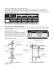
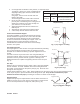
In addition to the configurations shown in Figs. 1 & 2, this system may be installed in any combination of vertical
and horizontal, enclosed and unenclosed configurations as long as minimum clearances are maintained per
clearance Tables 1 & 2 and the total length and number of fittings does not exceed the appliance manufacturer’s
recommendations. This system may also be installed within an existing masonry chimney.
Notes:
1. Unenclosed systems require at least one side open (combustible material on maximum of 3 sides).
2. Reduced clearances may be attained by using noncombustible enclosures.
3. Do not place insulation in any required clearance spaces surrounding the vent system unless these
instructions suggest otherwise and the insulation is specified or supplied.
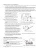
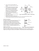
VENT ROUTING LIMITATIONS - MAXIMUM EQUIVALENT LENGTHS
In order to insure the vent system is not overly restrictive to flow, refer to the maximum length of vent specified by
the appliance manufacturer. In order to account for turns in the system (which cause additional resistance to
flow) most manufacturers recommend using an “Equivalent Length” method of determining the limitations. Via
such method, elbows and tees are assigned an “equivalent length” (in feet). If the sum of straight length segments
and additional “equivalent lengths” (due to turns) exceeds the limit specified by the manufacturer, the routing is
not permitted. See appliance manufacturer’s instructions for additional
information.
If the appliance manufacturer’s instructions do not list equivalent lengths for
standard fittings, use Table 3 to determine the Equivalent Length of the vent
fittings.
GENERAL INSTALLATION REQUIREMENTS
1. In instances where the appliance manufacturer’s instructions conflict
with requirements in this document, the appliance manufacturer’s
instructions take precedence.
2. Failure to conform to any of these requirements may violate local, state
or national codes as well as create conditions which may cause
catastrophic property damage and/or personal injury.
3. The horizontal vent connector must slope upward toward the termination at least 1/4 inch per foot and be
installed so that all condensate runs back toward the appliance or inline drain and is not retained in any part
of the venting system.
4. If called for by the appliance manufacturer’s instructions, a drain fitting must be located as close as possible
to the appliance flue outlet. Additional drains are required for each 30’ of vent. If a drain fitting is not
supplied with the appliance, install a Saf-T Vent in-line drain or a tee with a drain tee cover. Properly
dispose of collected condensate.
5. Multiple Category III or IV appliances may not be interconnected to any part of the venting system unless
the appliance manufacturer has specifically approved the engineering of the vent system. A Category III or
IV appliance may not be interconnected to any part of a vent system used with a natural draft or draft hood
appliance, except when a listed mechanical draft system is installed.
6. For venting systems that extend through any zone above that on which the connected appliance is located
(except for one and two family dwellings), codes require that the vent system be enclosed with an enclosure
having a fire resistance rating equal to or greater than that of the floor or roof assemblies through which it
passes. In one and two family residential construction the system must be enclosed whenever passing
through occupied spaces. The enclosure should be fabricated to allow periodic inspection of the vent.
7. Whenever gas-burning equipment is installed in the same space where halogenated substances may exist
(refrigerants, solvents, bleaches, salts, etc.), clean outside air must be utilized for combustion.
8. When passing 5’ or more of vent through an unheated area (such as attics, crawl spaces, building exteriors
or above roof lines), it is recommended that the system be converted to double wall CI Plus (or SC for 3”
and 4” pipe) to prevent condensation and freezing. Any penetrations of ceilings, floors, or walls must be
properly fire-stopped.
9. The vent system shall not be routed into, through or within any other actively used vent or chimney.
10. Another appliance may not vent into the flue space outside the Saf-T Vent conduit. However, if there is
sufficient space and all manufacturer’s instructions and codes are followed, a separate chimney liner may
be installed within the chimney to vent another appliance.
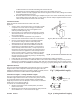
Equivalent Length Table
Fitting Equivalent
Length
Straight Length 1’ per 1’
Boot Tee 10’
90 Degree Elbow 10’
70 Degree Elbow 8’
45 Degree Elbow 5’
30 Degree Elbow 4’
15 Degree Elbow 3’
Table 3