
Installation Instructions


PI-EZINS 12/16/14
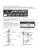
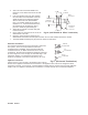
Fig 5. (Ring and Tab Connection)
Ring
Tab
Tabs Under Ring
Fold Tabs
Over Ring
HORIZONTAL INSTALLATION REQUIREMENTS
1. If the termination is through a combustible wall, the system must terminate with a Saf-T Vent Wall Thimble
and a Saf-T Vent termination as required by the appliance manufacturer.
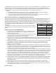
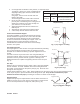
2. The horizontal termination shall be located not less than 12 inches above grade or anticipated snow line
(remember to consider snow and ice falling from overhead objects), and not less than 7 feet above grade
when located adjacent to a public walkway. It shall also terminate a minimum of 4 feet below, 4 feet
horizontally from, or 1 foot above any door, window, fresh air intake, utility meter or regulator unless the
appliance is Listed differently. The termination must be a minimum of 6 feet from the combustion air intake
of any other appliance. Proper judgment may require greater distances depending on the size of the
equipment installed or site conditions. Consult with the local Authority Having Jurisdiction.
3. The termination should be away from trees,
shrubs, or decorative items as flue gases
could cause damage.
4. The total equivalent horizontal distance of
the vent system from the appliance flue
collar to the outside of the termination shall
not be less than 14 inches.
5. A minimum of one (1) horizontal support is
required for every 6 feet of run.
VERTICAL INSTALLATION REQUIREMENTS
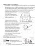
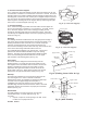
1. The vent system must terminate at least 3
feet above the roof line and at least 2 feet
higher than any portion of the building within
10 feet.
2. When terminated at a height of more than 6 feet above the roof, the vent must be supported by a Saf-T
Vent Guy Section. Refer to the Guy Support section of these installation instructions.
3. The vent system must terminate with one of the Saf-T
Vent Terminations; except when a Termination or
approved mechanical vent device is specified or
provided by the appliance manufacture.
4. The total continuous distance of the vent system from
the appliance flue collar to the termination shall not
exceed that specified in the appliance manufacturer’s
installation instructions. When venting natural draft
appliances the termination must be at least 5 feet
above the topmost draft hood. Otherwise a Listed
mechanical draft inducing device is required.
5. Vertical supports are required after every transition to
vertical and as specified in Table 4. Vertical supports
are also required above every offset elbow. See Table
4 for vertical support limits.
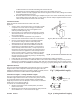
JOINT SEALING AND CONNECTION METHOD
Model EZ (Diameters 3" thru 16") is manufactured with a factory
installed seal on the inside of the female (outlet) end making the
use of any additional sealant unnecessary.
Connection
Note: It is required to apply gasket lubricant (p/n 7001SIL-5, sold
separately) to the factory installed silicone gasket when
assembling the pipe. Apply lubricant directly to the gasket on the
inside female pipe end, both edges of gasket.
1. Connect parts using the Ring and Tab Connection
Method. See Fig 5.
a. To connect, slide the lock ring away from the end
1 Ft. Above Doors & Windows
4 Ft. Horizontally from
Doors and Windows
4 Ft. Below any
window or fresh
air inlet.
7 Ft. Above Public
Walkways and Drives
1 Ft. above ground
or snow line
Sidewalk
Fig 3. (Horizontal Installation Requirements)
Fig 4. (Vertical Installation Requirements)
2'
10'
(2 Ft. Above Structures within 10 Ft.)