
Installation Instructions


PI-EZINS 12/16/14
to allow clearance for the tabs extending from the female end.
b. Engage the two sections making sure the tabs stay to the outside of the vent.
c. After the sections are fully engaged, slide the lock ring down over the tabs, making sure all tabs
are contained within the lock ring.
d. Bend the tabs back over the lock ring to complete the joint. Note: Some termination parts have a
hose clamp in place of the lock ring. In such cases, the hose clamp is tightened down over the
tabs. The tabs need not be bent over the clamp.
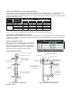
Condensate Drains:
When An Internal Condensate Drain Is NOT Part of the
Appliance:
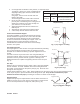
x A Saf-T Vent In-Line Drain Section, Tee or Boot Tee with
a separate Tee Cover Drain is strongly recommended.
Install this drain fitting as close to the appliance flue
collar as possible (See Fig. 6A).
x Use the Boot Tee to transition from horizontal to vertical
and attach the Drain Tee Cover to the appropriate leg of
the tee (See Fig 6A).
x A condensate drain is required for every 30 feet of
horizontal vent and at/near the bottom of a vertical stack.
x Use the In-Line Drain Section for a straight horizontal
run. Rotate the fitting so that the drain tube points
downward and is as vertical as possible (See Fig. 6B).
x A Condensate Drain Tube Kit is available to drain the
condensate to an appropriate location (i.e. floor drain or
vented sanitary sewer connection). A trap loop must be
formed into the drain hose and must be a diameter that is
at least four times the appliance's rated stack pressure in
inches of water column or 3 inches, whichever is greater.
Secure the loop with a cable tie. Prior to final assembly
the trap loop must be 'primed' by pouring a small quantity
of water into the drain hose.
x Follow all local and national codes and regulations for the draining of acidic condensate.
x In cold climates do not install a condensate drain on the exterior of the building. Doing so may result in
dangerous icy conditions on surfaces near the drain and may cause damage to the vent system and/ or
the building exterior. We will NOT be held liable for any injury or property damage due to formation of ice.
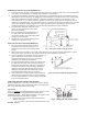
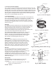
Adjustable Section:
The Saf-T Vent EZ Seal Adjustable Length Section serves as a variable
length between other components when specific lengths cannot be
utilized and eliminates the need to cut parts to length. To install, refer to
installation instructions included with the Adjustable length.
Customized Lengths— Cutting Standard Lengths
The Saf-T Vent EZ Seal system is designed so that in most cases
standard lengths will not need to be cut. There may arise, however,
an occasional situation where standard lengths and adjustable
length slip connectors are not adequate. In such cases, a standard
length of Saf-T Vent may be field cut.
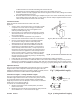
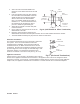
To custom cut a standard length part:
1. Measure the length of vent needed (Dim A) and add 3
inches to the result.
2. Measuring from the female end (end with the tabs) measure
out the distance A + 3" and mark it on the pipe.
Fig 7. (Adjustable Length)
Fig 6B. (In-Line Drain Sectionand Drain Tube)
Fig 6A. (Boot Tee w/ Drain Cover & Tube)
Boot Tee
Drain Tube
Drain Tube
w/ Trap Loop
Drain Section
A + 3"
Cut Here
A
Non-Standard Length
Required
Fig 8. (Cutting Standard Lengths)
Standard Length