
Installation Instructions


PI-EZINS 12/16/14
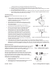
3. Cut the pipe with an abrasive cutoff, plasma, or compound snips.
To help get a square cut, create a straightedge by
wrapping masking tape around the waste side of
the cut point. If
using snips, start the cut at the male end and
follow a spiral path
around the pipe until the cutoff mark is reached.
1. File off any burrs that develop in the cutting
process prior to assembling. If the cutting process
distorts the roundness of the pipe carefully use
your thumbs to re-round the end.
2. Apply high-temperature silicone sealant to the
field-cut joint.
3. Assemble the joint using the procedures above.
4. A hose clamp must be used to retain the tabs.
Vertical and Horizontal Support
For proper installation, Vertical and/or Horizontal supports
must be installed to support the Saf-T Vent. Refer to Table
4 for minimum spacing distances and the corresponding
section for instructions for installing the support. Note: For
all support options, ensure all minimum clearance to
combustibles are maintained. Never drill or screw through
the Saf-T Vent system.
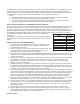
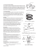
Guy Support Section
The Guy Support is a short section of vent pipe with brackets protruding
from it. These brackets provide a means for attaching a guy line,
threaded rod or similar metal bracing to provide support to the vent
system.
To Install: Connect Guy Section to the vent using standard joint
connection method. Attach guy wires or metal bracing to the brackets
provided on the Guy Section. Anchor guy wires or bracing to the
building infrastructure capable of supporting the load of the vent (See
Fig. 9).
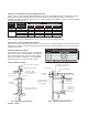
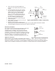
Fire Stop
Wherever the vent passes through a ceiling or floor a Fire Stop (5x18CI)
must be installed. To Install: Establish the correct framing dimension
(See Table 1) and nail the Fire Stop to the joist (Fig 10). Route the vent
through the Fire Stop plate.
Caution about insulation in attics – Note: When installing a Fire Stop in the attic, the Fire Stop should be located
on the top of the joist to prevent insulation from falling into the joist. Keep all attic insulation the proper
minimum clearance from pipe by installing an enclosure or similar around the pipe.
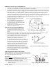
Support Clamps
Support Clamps may be suspended from rods or cables and used as a
saddle to rest the vent in or they may be used in pairs to clamp around
the vent and suspended from a single rod, cable (See Fig. 11).
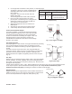
Spacing Between Supports
Diameters
Vertical
Spacing
Horizontal Spacing
3” thru 5” 30’
Every six (6) feet and
after every transition from
vertical to horizontal.
Table 4. (Vertical and Horizontal Support
Requirements)
Fig 10. (Firestop/Support)
Firestop
Plate
Support
Clamp
Saf-T Vent
Framed
Opening
Pair of Support Clamps
Support Clamp
Fig 11. (Support Clamps)
Anchor Bracket
Fig 9. (Guy Support Assembly)
Guy Support Section
Guy Wire
Fig 10. (Fire Stop)