
User's Manual

The CFIP Series Full Outdoor Unit Installation Manual • Rev. 1.3 • Software version 1.42b
© SAF Tehnika JSC 2010
6
– Necessary tools for assembling the optical or Ethernet cables, power cables and
connectors (not included)
2.2.2 Antenna Installation Tools
– Voltmeter/multimeter with corresponding BNC adapter (not included);
– Mounting bracket and necessary wrenches, nuts, screws and clamps;
– Binoculars and compass for clear sight installation (not included).
2.3 Labels
2.3.1 CFIP Lumina Label
The label can be found on the front side of the unit.
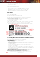
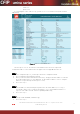
The label contains the following information (see samples in the picture below):
- Model name (“CFIP-18-Lumina”). The FODU model name example is:
- CFIP-13-Lumina for 13GHz FODU,
- CFIP-23-Lumina for 23GHz FODU, etc, where:
xx - frequency band of the FODU.
- Product Number (I18GHT03L): product number contains information in which band
side (L, H) the FODU operates. Letters A, B, C or D indicate specific subband.
– Unit Serial Number (3203601 00005); the serial number uniquely identifies the unit.
Figure 2.
Label of the CFIP Lumina High band side, operating in 18 GHz band
3 Installing CFIP Lumina Full Outdoor Unit (FODU) radiolink
The installation of CFIP Lumina link involves the following steps:
1. Initial equipment set up at the customer’s premises
– Unpack all equipment;
– Prepare necessary cables;
– Provide power to CFIP Lumina using appropriate power supply – 48V, any polarity, at
least 35W of load power;
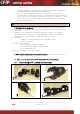
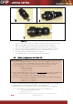
– Interconnect CFIP Lumina’s with use of test suite (coaxial cable, attenuator,
waveguide-to-coaxial adaptors).
Although testing suite is highly recommended, if it is not available, establish the link
by turning CFIP Lumina’s of one hop against ceiling (with flanges facing upward) and
set minimum Tx power available.
2. Connecting to Web interface management or serial terminal through Ethernet
bridge port or serial management port in order to configure the equipment.