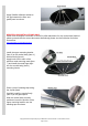
SS1410HF SAFARI V-SPEC SNORKEL VOLKSWAGEN AMAROK V6 TDI550 3.0L TDI V6 Engine 01/07/2017 Parts List ITEM PART NO. DESCRIPTION 1 910-133-000 BODY - SNORKEL (SS1400HF) 1 2 000-135-800 3 ½" AIR RAM ASSEMBLY 1 3 910-032-000 BRACKET - UPPER MOUNTING 1 4 000-002-100 BOLT - HEX - 6mm x 1.0 x 14mm (SEMS) 2 5 000-951 SCREW - S/T - 4.2mm x 13mm - S/S 3 6 000-960 INSERT - PLASTIC 3 7 000-110 STUD - 8mm x 1.
17 000-300-350 WASHER - BODY - 4mm x 12mm - S/S 4 18 910-959-000 CAP - AIR INLET BLANK-OFF 1 19 000-908 CLAMP - HOSE - 70/90mm 1 20 000-910 CLAMP - HOSE - 90/110mm 1 21 000-914/B CLAMP - HOSE - No. 56 (BLACK) 1 22 910-967-200 PLATE - INNER GUARD SUPPORT 1 23 910-967-650 PLATE - INNER GUARD SUPPORT SPACER 1 24 000-958-525 POP RIVET - 4.
SS1410HF SAFARI V-SPEC SNORKEL VOLKSWAGEN AMAROK V6 TDI550 3.0L TDI V6 Engine Installation Guide Fitment to: • Special Tools: Right Hand Side Fitting Time: • 210min • • • • • • 83mm Hole saw Body Saw (Reciprocating) Step Drill 4.0mm & 5.
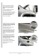
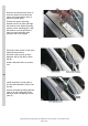
3 Align the guard panel template (Item 29) to the rear and upper edges of the right hand guard panel. Tape the template to the guard panel with masking tape. Mark all six mounting hole positions the two hole saw centre positions and the upper and lower cut out sections with a felt tip pen. Remove the template. 4 Apply masking tape to guard panel and flare to ensure no metal filings are trapped between the flare and guard panel as shown. Drill a pilot hole for each of the marked hole positions.
Apply Sikaflex adhesive sealant to the gap between the flare and guard panel as shown. NEW ZEALAND INSTALLATIONS ONLY : Safari have developed 2 methods of Snorkel A pillar attachment, for the conventional method please proceed with the current document alternatively please see the link below for further instructions. www.safari4x4.co.nz/apillarmounting 6 Install the upper mounting bracket (item 3) to the snorkel body (item 1) with hex bolts (item 4).
8 Remove the snorkel body (item 1) from the vehicle and remove the upper mounting bracket (item 3) from the snorkel body. Position the upper mounting bracket onto the A-pillar and align the bracket to the marked bracket position on the masking tape. With the bracket correctly positioned mark the three mounting hole positions with a felt tip pen. 9 Drill a pilot hole at each of the three marked hole positions. Drill each hole position to 8mm diameter with a step drill or 8mm drill bit.
11 Unclip the wiring loom and coolant by-pass hose from there mounting positions, align the inner guard template (item 28) to the top edge, wiring loom mounting hole and the coolant by-pass rectangle mounting slots of the inner guard panel as shown. Tape the template to the inner guard panel with masking tape. Ensure the template follows the contours of the inner guard panel.
14 Align and tape the inner guard support spacer plate (item 23) to the inner guard support plate (item 22) Install the inner guard support plate and spacer plate to the inner guard panel, loosely install four pop rivets (item 24) to hold the support plate in position. Using a felt tip pen or the 5.0mm drill bit mark the four mounting hole positions onto the inner guard panel. Remove the pop rivets, inner guard support plate and spacer plate.
17 Apply a smear of Sikaflex adhesive sealant to the inner guard support spacer plate (item 23), align the spacer to the two holes in the support plate and press down firmly. 18 Apply a generous amount of Sikaflex adhesive sealant to the inner guard support plate (item 22) and spacer plate (item 23). 19 Install the support plate and spacer plate with Sikaflex adhesive sealant applied to the inner guard panel, install all eight pop rivets and secure the support plate and spacer to the inner guard panel.
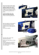
20 Measure down 25mm from under the air cleaner base top shoulder and mark the five air cleaner base ribs as shown. Use a grinder or sharp knife to remove the lower sections of the 5 ribs from the side of the air cleaner base. 21 Align the air cleaner inlet template (item 25) onto the side of the air cleaner base as shown. Mark all four hole positions with a paint marker pen. Remove the template. 22 Align the air cleaner inlet template (item 26) onto the side of the air cleaner base as shown.
23 Align the lower air cleaner inlet template (item 27) onto the underside of the air cleaner base as shown. Mark all four hole positions and cutout section with a paint marker pen. Remove the template. 24 Using a 4.0mm drill bit, drill all 12 marked hole positions. Using the body saw cut the new air inlet hole as marked from the templates in steps 22 & 23. Use a file to clean-up the cut section, deburr all drilled holes.
26 Apply adhesive sealant to the mating surfaces of the air entry hose. Install the air entry hose onto the air cleaner base, install the upper, sides and lower clamping plates (item’s 11, 12, 13 & 14) to the hose, install the air filter support plate (item 15), install all twelve pop rivets (note: the orientation of the four lower pop rivets), install a 4mm body washer (item 17) to the four lower pop rivets as shown. 27 With all twelve pop rivets install, use the pop rivet gun to secure the pop rivets.
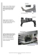
28 Install the air inlet blank-off cap (item 18) over the air cleaner inlet snout, with the blank-off cap correctly installed secure with a 70/90mm hose clamp (item 19), ensure the hose clamp is positioned to the rear edge of the blank-off cap. 29 Install the coolant bypass hose into its mounts and position the wiring harness along the inner guard panel. 30 INSTALLER OPTION: The air cleaner housing contains a drain valve as shown. The serviceability of the drain valve must be check by the installer.
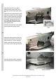
31 The end of the air entry hose (item 10) must be squashed inwards and taped to hold in position as shown. N.B: it is critical the hose is taped the way shown in the photo, for installation purposes. 32 With the hose correctly taped, spray lubricant over the outside of the hose.
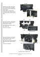
33 Shape the 90/110mm hose clamp (item 20) to the oval shape of the air entry hose, loosely install the hose clamp onto the air entry hose. Carefully install the snorkel body (item 1) to the guard panel, guiding the snorkel body outlet snout into the air entry hose (item10), align the snorkel body to the guard panel and upper mounting bracket. When correctly aligned, fasten the snorkel body to the guard panel with body washers (item 8) and nyloc nuts (item 9).