SS165HF SAFARI V-SPEC SNORKEL Holden Rodeo RA-7 – 4JJ1 Engine 10/04/2007 ITEM PART NO DESCRIPTION QTY 1 735-133-000 BODY - SNORKEL (SS165HF) 1 2 000-135-650 3 1/2" AIR RAM ASSEMBLY 1 3 730-032-000 BRACKET - UPPER MOUNTING 1 4 000-002-100 BOLT - HEX - 6mm x 1.0 x 14mm (SEMS) 3 5 000-958-350 POP RIVET - 4.8mm x 14mm 3 6 735-124-000 INNER DUCT (SS165HF) 1 7 000-110 STUD - S/S - 8mm x 1.25 x 25mm 3 8 000-311 WASHER - BODY - 8mm x 30mm 3 9 000-205 NUT - NYLOC - 8mm x 1.
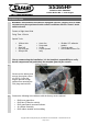
SS165HF SAFARI V-SPEC SNORKEL Holden Rodeo RA-7 – 4JJ1 Engine Installation Guide WARNING: On automatic transmission equipped vehicles, a higher level of intake resonance may be experienced under certain conditions with the "Power" mode switch selected.
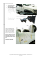
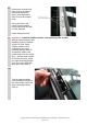
Remove and Discard: • • • Air entry duct from the inner guard. 3.0 VCDi guard panel mounted badge (use heat gun sparingly to soften the badge adhesive and prepwash to clean sticky residue). Pre-spinner from air cleaner housing. 4 Tape the template (Item 16) to the rear and upper edges of the RHS guard panel using the indicator hole as a reference point. With the template correctly positioned, mark all of the hole positions with a felt tip pen. Remove the template.
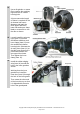
5 Drill a pilot hole for each marked hole position. Drill the main hole in the guard panel with a 105mm hole saw. Drill the 3 mounting hole positions to 16mm with a step drill. Deburr and paint holes to prevent rust. 6 Apply Loctite to all three studs (Item 7) and install the studs into the snorkel body mounting inserts (Item 1). 7 Fasten the upper mounting bracket (Item 3) to the snorkel body (Item 1) with 6mm hex bolts (Item 4).
8 Remove the snorkel body (Item 1) from the guard panel and remove the upper mounting bracket (Item 3) from the snorkel body. Drill a pilot hole in the centre of each marked hole position and then drill to 5mm diameter. Deburr and paint holes. 9 Important! - Install the Rubber weather seal moulding to the A-pillar.
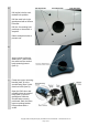
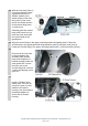
11 Use a die grinder or coarse file to remove the retaining lugs from the air cleaner housing inlet. A hose connection length of 30mm is required on the air cleaner inlet snout. Measure and mark the three upper and three lower ribs and use a sharp blade or coarse file to trim the ribs as shown. 12 Loosely install the air entry hose (Item 11) and the 80/100mm stainless steel hose clamp (Item 12) onto the modified air cleaner housing inlet.
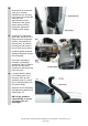
14 With the inner duct (Item 6) correctly positioned, apply a generous amount of Sikaflex sealant to the inside surface of the inner duct (Item 6) inlet snout and to the outside surface of the snorkel body (Item 1) outlet snout. Carefully guide the snorkel body outlet snout into the inner duct inlet and install the snorkel body to the guard panel. 15 Align the snorkel body to the upper mounting bracket and guard panel.
18 Ensure that the inner duct (Item 6) is correctly installed into the air entry hose (Item 11) and that the inner duct has approximately 10mm clearance to the guard panel. When correctly positioned, tighten the 70/90mm hose clamp. 19 Install the ECU and with great care, install the ECU plugs into their respective sockets. Reinstall the air filter element, air cleaner housing top and connect the air mass sensor plug. Install the guard mounted indicator lamp and connect the wiring plug.