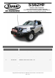
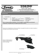
SS62HF SAFARI V-SPEC SNORKEL Nissan Y62 Patrol (February 2010 to April 2019) 4.0Litre-V6 & 5.6Litre-V8 Petrol (VQ40DE & VK56VD Engines) Note: Does not suit MY20 Series 5 Facelift \ 01/03/2019 Parts List ITEM PART NO. DESCRIPTION 1 490-133-000 BODY - SNORKEL (SS62HF) 1 2 000-135-960 4” AIR RAM ASSEMBLY 1 3 490-032-000 BRACKET - UPPER MOUNTING 1 4 000-002-100 BOLT - HEX - 6mm x 1.0 x 14mm (SEMS) 2 5 000-1024-300 BOLT - B/H 5.0mm x 0.
13 000-1911 CLAMP - HOSE - 100/120mm - S/S 1 14 490-025-000 PLATE - HOSE SUPPORT - Main - S/S 1 15 490-025-100 PLATE - HOSE SUPPORT - Lower - S/S 1 16 490-025-200 PLATE - HOSE SUPPORT - Side- S/S 1 17 000-958-175 POP RIVET - 4.0mm x 17mm 10 18 000-094-300 BOLT - B/H 4.0mm x 0.7 x 20mm - S/S 3 19 000-300-350 WASHER - BODY - 4.0mm x 12mm - S/S 3 20 000-223-300 NUT - NYLOC - 4.0mm x 0.
SS62HF SAFARI V-SPEC SNORKEL Nissan Y62 Patrol (February 2010 to April 2019) 4.0Litre-V6 & 5.6Litre-V8 Petrol (VQ40DE & VK56VD Engines) Note: Does not suit MY20 Series 5 Facelift Installation Guide Fitment to: Special Tools: • • • • • Left Hand Side Fitting Time: • 210min • • • • Rivet Nut Gun: Wurth article no: 0949 16 or one • Body saw (reciprocating) Step drill 4.5mm, 7.0mm, 14.5mm Drill Bits Rivet Nut Pliers/Gun with a head size no larger than 14mm diameter.
3 Remove and Discard the Left Hand fender vent. 4 Remove and discard the perforated section of the guard panel template (item 26) as shown. 5 Align the guard panel template (Item 26) to the upper and rear edges of the Left Hand guard panel as shown. Tape the template to the guard with masking tape. Mark all hole positions and the cut-out section with a felt tip pen. Remove the template. Copyright Safari 4x4 Engineering Pty Ltd Melbourne Victoria Australia – www.safari4x4.com.
6 Drill a pilot hole for each of the marked hole positions. Use a step drill to drill the 6 mounting holes to 16mm diameter. Drill 2 or 3, 10mm diameter holes in the cut-out section for a start/stop point for the body saw, using the body saw cut the main hole in the guard panel as marked from the template cut-out in step 5. Deburr and paint all holes. 7 Align the internal panel template (item 25) as shown to the lower edge and double panel, mark the cut-out and remove the template.
9 Install the upper mounting bracket (Item 3) to the snorkel body (Item 1) with hex bolts (Item 4). Apply Loctite 243 to each of the stainless steel mounting studs (Item 9) and install the studs finger tight into the snorkel body (item 1) mounting inserts as shown. 10 Place a strip of masking tape along the plastic Apillar trim. Carefully install the snorkel body (Item 1) to the guard panel.
12 Drill a pilot hole for each of the three marked hole positions, through the plastic A-pillar trim and through the steel A-pillar panel below. Drill both the plastic A-pillar trim and the steel A-pillar panel holes to 7.0mm diameter with a 7.0mm drill bit. Using compressed air remove the metal swarf from the A-pillar trim cavity. 13 Using a 14.5mm drill bit, drill the three holes in the plastic A-pillar trim to 14.5mm diameter. Note: Do not drill into the steel A-pillar Panel.
15 Install the three A-pillar bracket spacers (item 7) into the plastic A-pillar trim. Install the upper mounting bracket (item 3) and secure to the A-pillar with M5 x 25mm button head bolts (item 5) with M5 x 15mm body washers installed (item 6). 16 Remove and discard the foam sealing tape from the air cleaner inlet snout. 17 Align the side cutting template (item 23) to air cleaner base inlet snout as shown, mark the cut line and remove the template.
18 Align the side template (item 22) onto the air cleaner base mounting bracket as shown, mark the two hole positions. Remove the template. 19 Align the main air cleaner template (item 21) to the 1st rib, around the air cleaner clip mount and under the top section of the air cleaner base, with the template correctly aligned tape the template to the air cleaner base, mark all hole positions and the required cut out as shown. Remove the template.
20 Drill a pilot hole for each of the marked hole positions, using a 4.5mm drill bit, drill all the holes to 4.5mm diameter. Using the body saw, cut the new air cleaner base inlet hole as marked from the templates. Note: Cutting on the outside of the marked lines. Using a file, deburr the cut edges of the new air cleaner base inlet hole. 21 Using the body saw trim off the 5 upper ribs on an angle as shown. Using the body saw / sharp knife completely remove the side rib as shown.
22 Install the air entry hose (item 12) onto the air cleaner base, align the hose to the 4.5mm diameter holes, with the hose correctly positioned drill the two remaining air entry hose mounting holes with a 4.5mm drill bit. 23 The main and lower hose support plates (items 14 & 15) require bending, align each of the plates onto the air entry hose (item 12) and bend the support plates to the profile of the air entry hose mounting flange as shown.
24 Apply adhesive sealant to the mating surfaces of the air cleaner base and air entry hose (item 12). Install the air entry hose (item 12) onto the air cleaner base, install the main and lower hose support plates (item’s 14 & 15) to the hose, install all ten pop rivets (item 17) from the inside of the air cleaner base, with the pop rivets installed, use a pop rivet gun to secure all ten pop rivets as shown.
26 INSTALLER OPTION: VQ40DE V6 Engine: Air cleaner base contains a drain valve as shown. VK56VD V8 Engine: Air cleaner base contains a drain hole as shown. These can permit water to enter the air intake. Safari advises that the drain valve or drain hole should be sealed to ensure a watertight installation. 27 Squashing the end of the air entry hose inwards, install the air entry hose through the hole in the inner guard panel, with the air cleaner base correctly installed into the vehicle.
28 Apply lubricant to the inlet of the air entry hose (item 12). Carefully install the snorkel body (item 1) to the guard panel, guiding the snorkel body outlet snout into the air entry hose (item 12). Align the snorkel body to the guard panel and upper mounting bracket, fasten the snorkel body to the guard panel with body washers (item 10) and nyloc nuts (item 11). Fasten the snorkel body to the upper mounting bracket with hex bolts (item 4).
30 Loosely install the black hose clamp (Item 24) to the base of the air ram assembly (Item 2). Install the air ram assembly onto the snorkel body (Item 1). Align the air ram assembly and tighten the black hose clamp (Item 24). 31 Install the inner guard liner, mud flap, factory side step, air filter element, air cleaner lid, reconnect sensor wiring and any other items that may have been removed in accordance with the factory service manual. 32 N.