
Specifications


On the radio PCB is the final stage of transmit audio processing. The UHF issue C version of
this board uses a discrete transistor active low pass filter realized by transistors TR415, and
TR416.
This filter is a fourth order low pass with a 3kHz cutoff frequency set by C545, C547, C548
and C549. The output of TR423 emitter connects directly to the transmit VCO for modulation.
Trim potentiometer R567 provides an adjustable level to modulate the reference oscillator.
This adjustment sets the balance for the two point modulation.
For the VHF and UHF issue E radio PCB assemblies the low pass active filter is realized by a
dual OP AMP IC406.
The first stage is configured in a unity gain low pass filter with a cut-off frequency of 3kHz. The
output of the filter is at the junction of R564 and C549 and connects directly to the transmit
VCO modulation input. The second stage is used as a buffer amplifier to drive the modulation
input of the reference oscillator. R567 sets the modulation balance.
3.2.3 Synthesizer
3.2.3.1 GENERAL
The function of the synthesizer is to provide two stable signal sources of high spectral purity.
These signals are for the functions of receiver local oscillator and the primary excitation of the
transmitter power amplifier.
It is very important to obtain a low single-side-band phase noise for both of these signal
sources to achieve the required levels of receiver and transmitter performance.These
objectives have been achieved by utilizing a single phase locked loop with a high gain phase
comparator and independent receive and transmit low noise VCOs.
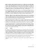
3.2.3.2 THE BASIC PHASE LOCKED LOOP SYNTHESIZER
Refer to figure 3.6.
In operation, a voltage controlled oscillator (VCO) produces an output signal at frequency Fo;
this frequency is divided down to Fo/N by a programmable divider. A reference oscillator
output is also divided down by a programmable divider to produce the synthesizer reference
frequency Fr. This frequency is the lowest common denominator which is divisible into all of
the required final frequencies (Fo) there are to be programmed. It also becomes the minimum
frequency increment of the final frequency.
The signals of Fo/N and Fr are combined in a phase comparator which produces an output
voltage proportional to the phase error between these two inputs. The error signal is
connected via the loop filter circuit block, back to the voltage control input of the VCO. The
error signal causes the VCO frequency to be modified so that no phase difference exists
between the two phase comparator inputs. When this occurs the loop is said to be phase
locked and Fo/N = Fr.
Section 3 Page 12