
User's Manual
Installation and Operation Manual
STI Universal Sensor
Model: STI-34401
U-Sensor Setup:
1. Open device using a flat head screwdriver in the slot under the case.
2. Configure the jumpers for the desired application. (See Jumper Configuration)
3. Insert 3V lithium 123A size battery in the proper orientation.
4. Program the STI Universal Sensor into the STI receiver.
NOTE: Please refer to the STI receiver installation instructions for this.
5. Place the Tamper Switch Spring onto tamper switch after jumpers have been
configured and battery has been inserted. Tamper alert is triggered when spring
releases. Intended to identify when case is opened/broken/ajar.
6. Snap base into lid. Ensure that Tamper Switch Spring is within the Spring
Locator circle on the lid and compresses when the lid is snapped shut.
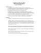
Mounting:
OPTION 1: Mount with double sided tape (provided) to the back of the case.
OPTION 2: Remove the circuit board from the case bottom. Drill 1/8” holes
through the case knock outs and in the mounting locations, and apply the screws
(provided). For added protection, cover metal screw heads on the inside of the
case bottom with electrical tape to isolate the circuit board. Replace the circuit
board in the case bottom.
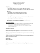
When using the Magnetic Sensor, the bottom case may be inserted into the top
case in reverse depending on which direction the Magnetic Sensor should face.
When using the Tilt Sensor, the arrow on the bottom should point straight up in
the non-triggered state.
When using the External Terminals, remove the case knock out in the corner of
the case bottom to insert sensor wires.
(Note: Do not use outdoors when using External Terminals)