
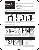
Instructions / Assembly

䊴
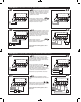
A1 Connect the hot lead of the input volt-
age (24 VAC, 60 HZ) to terminal 1. Connect the
neutral lead to terminal 2. 24 VAC, 60 HZ must
be supplied to terminals 1 and 2 for internal
operation of the control.
Install a jumper between terminal
A2
䊳
1 and terminal P1. Power from terminal P1 is
supplied to terminal P2 through the control
relay when water is at the probe.
P1 P2 A
+
0
LIMIT
CONTROLS
BURNER
CIRCUIT
NEUTRAL
HOT
2
1
ALARM
P1 P2 A
HOT
BURNER
CIRCUIT
NEUTRAL
2
1
BURNER
POWER
SOURCE
(
24 or
120V
AC
)
P1 P2 A
BURNER
POWER
SOURCE
24V
AC
60HZ
2
1
2
P1 P2 A
BURNER
POWER
SOURCE
24V
AC
60HZ
1
NEUTRAL
HOT
P1P2 A
NEUTRAL
HOT
BURNER
+
0
LIMIT
CONTROLS
2
1
2
P1 P2 A
BURNER
POWER
SOURCE
24V
AC
60HZ
1
NEUTRAL
HOT
P1 P2 A
+
0
LIMIT
CONTROLS
BURNER
CIRCUIT
HOT
NEUTRAL
2
1
1
P1 P2 A
ALARM
WIRING METHOD A: SAME POWER SOURCE FOR CONTROL AND BURNER CIRCUIT.
䊴
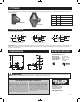
B1 Connect the hot lead of the input
voltage (24 VAC, 60 HZ) to terminal 1. Connect
the neutral lead to terminal 2. 24 VAC, 60 HZ
must be supplied to terminals 1 and 2 for inter-
nal operation of the control.
Connect hot lead from the 24 VAC
or 120 VAC burner power source to
terminal P1. This terminal supplies power to ter-
minal P2 in normal operating conditions when
water is at the probe. Connect neutral to burner
circuit. Note: consult boiler manufacturer
instructions for proper terminal connections.
䊴
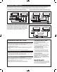
A3 Connect terminal 2 to burner circuit
neutral. Connect terminal P2 to burner circuit in
series with other limit controls. Consult boiler
manufacturer instructions for proper terminal
connections. Control should be wired in series
with and before other circuits.
Optional alarm connection.
A4
䊳
Connect alarm common to terminal 2.
Connect alarm hot to terminal A.
Upon completion of wiring, replace control
box cover.
䊴
B3 Connect terminal P2 to burner
circuit in series with and before other limit con-
trols.
Optional alarm connection. Connect
B4
䊳
alarm hot to terminal A. Connect alarm common
to neutral of the burner power source.
Upon completion of wiring, replace control
box cover.
A1
A2
A3 A4
B1
B3
B2
B4
WIRING METHOD B: SEPARATE POWER SOURCE FOR CONTROL AND BURNER CIRCUIT.
B2
䊳