
Instructions / Assembly
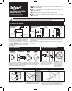

WIRING METHOD C: SECONDARY CUT-OFF
SAME POWER SOURCE FOR CONTROL AND BURNER CIRCUIT
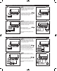
ALTERNATE WIRING: SECONDARY CUT-OFF WITH CRITICAL DIFFERENTIAL
SEPARATE POWER SOURCE FOR CONTROL AND BURNER CIRCUIT
OPERATING INSTRUCTIONS
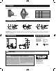
700 Series: Manual Reset
1. With the water level above the probe, turn on the power and set the thermostat to call for
heat. The burner will fire immediately. The LED lamps should be off.
2. Slowly lower the water level below the probe. The amber light will come on and the burner
will shut down within two seconds.
3. Wait 3O seconds. The red LED lamp will come on indicating that the control is locked-out.
4. Raise the water above the probe. The red LED lamp will remain lit and the burner will
not fire.
5. Push the RESET button to reset the control and restore burner operation.
600 Series: Automatic Reset & Test Button
1. With the water level above the probe, turn on the power and set the thermostat to call for
heat. The burner will fire immediately. The LED lamp should be off.
2. Push the test button on the top of the control to simulate a low water condition. The LED
lamp will light and the burner will shut down within two seconds.
500 Series: Manual Reset & Test Button
Follow the operating instructions for the 700 & 600 Series above.
Note: To test the manual reset feature on the 500 Series without lowering the water level:
1. Push and hold down the TEST button. The red LED lamp will come on in approximately
3O seconds indicating that the control is locked-out.
2. Once the red LED is lit, release the TEST button. The burner will not fire.
3. Push the RESET button to reset the control and restore burner operation.
TROUBLE SHOOTING
IF THE BURNER DOES NOT SHUT DOWN
If the burner does not shut down when the water drops
below the probe:
1. Remove power immediately and re-check wiring.
2. Remove power and check for adequate clearance from
the probe to any surface within the boiler or tee.
IF THE BURNER DOES NOT FIRE
1. Make sure water is at probe and probe lead wire is
properly secured to the terminal.
2. Check for proper ground between probe and boiler
shell. Excessive use of Teflon tape or sealing com-
pound may insulate the probe from the boiler shell.
3. Re-check wiring and test for correct incoming voltage.
IF THE RED LED LAMP IS ON
The red LED lamp indicates that the control is locked-out.
This feature will activate if the boiler experiences a low
water condition exceeding 30 seconds in duration.
IMPORTANT: Do not reset control until the cause of the
low water condition is corrected. CAUTION: Do not add
water until boiler is cool.
MAINTENANCE
To ensure optimum performance, inspect probe annually.
Clean any scale or build-up from the probe using a scour-
ing pad or steel wool. Re-install the probe and test control
in accordance with the Operating Instructions.
When a Safgard 500/700 is used as a secondary low water cut-off on a steam boiler, the following wiring instructions should be used. The diagram below
depicts the 500/700 as a secondary control wired in series with a Safgard Model 400/CG400. Consult boiler manufacturer’s instructions for the location of a
tapping recommended for a secondary low water cut-off. CAUTION – Model 500/700 should not be used as a primary cut-off on a steam boiler.
On some installations it may be necessary to mount the secondary cut-off at a
level in close proximity to the primary cut-off level. In these situations, when
the primary low water cut-off shuts down the boiler, the water line can settle
below the secondary cut-off causing nuisance lockouts. The wiring diagram at
the right is designed to prevent these lockouts. NOTE: This wiring method can
only be used if the power supply from the primary cut-off is 24 VAC.
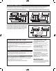
2 1
P1P2 A
2 1
P1P2 A
24 VAC
+
0
BURNER
CIRCUIT
LIMIT CONTROLS
MODEL 400/CG400 MODEL 500/700
ALARM
PRIMARY CUTOFF SECONDARY CUTOFF
FEEDER
NEUTRAL
HOT
21
P1 P2 A
21
P1 P2 A
NEUTRAL
HOT
MODEL 500/700
PRIMARY CUTOFF SECONDARY CUTOFF
NEUTRAL
BURNER
CIRCUIT
TO
BURNER
POWER FROM
PRIMARY CUT-OFF
24 VAC
+ 0
LIMIT CONTROLS
MODEL 400/CG400
21
P1 P2 A
21
P1 P2 A
BURNER
SUPPLY
VOLTAGE
+
0
LIMIT CONTROLS
MODEL 400/CG400 MODEL 500/70
BURNER
CIRCUIT
24 VAC
ALARM
PRIMARY CUTOFF SECONDARY CUTOFF
FEEDER
NEUTRAL
HOT
HOT
NEUTRAL