
Specifications


Chapter 11: Typical Connection Diagram
Firmware – S2011 and S3012
Revision: 1 (9/98) 80 © Saftronics, Inc.
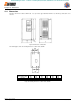
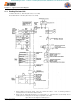
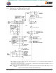
11.1 Braking Resistor Unit
For Models GP5 23P7 to − GP5 27P5 (200 V Class 3.7 to 7.5 kW).
Models GP5 40P4 TP − GP5 4015 (400 V Class 0.4 to 15 kW).
= The transformer is not necessary for 200V class.
‡ When installing a DC Reactor (option), remove the common bar between ¾1 and ¾2 terminals (provided as
standard) and connect a DC Reactor with the terminals.
# When using the Thermal Overload Relay, set constant n070 to 0. (Stall Prevention selection during decel is
disabled.) If it is not changed, the Inverter may not stop within set decel time.
Figure 54 Connection Diagram for Braking Resistor
GP5
efesotomasyon.com - Control Techniques,emerson,saftronics -ac drive-servo motor