MC-MAC-4R Hardware Installation Guide REV 2.
Table of Contents Chapter 1: The MAC-4R......................................................................................................................................... 5 MAC-4R Design & Layout........................................................................................................................................ 5 Compatible Readers................................................................................................................................................
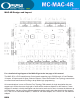
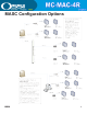
MAC-4R Design and Layout For a detailed wiring diagram of the MAC-4R got to the last page of this manual. The MAC-4R is a PLC based Access Control panel supporting up to 52,000 cards, 4 Card Readers, 16 Inputs, 8 Outputs and 16 Open Collector Outputs. It uses the Echelon Free Topology transceivers to communicate and features full Drag-n-drop ladder logic programming. All communications is over an Echelon Free Topology 78kb network.
COMPATIBLE READERS: The MAC-4R controller supports many different styles of Wiegand based readers. The bit structure can vary to support 26, 29, 32, 34, 35, 36, 37, 40, and 48 bits cards. Multiple formats are support simultaneously. The following readers were determined to be compatible with the MAC-4R Intelligent Controller.
WIre Terminations All terminations are via plug-in connectors. All field wire connectors are screw-terminal compression type, accepting up to #14AWG solid or stranded wire. Stranded-type wire is recommended. If solid-type wire is to be used, it is recommended that wire be no larger than #18AWG. Strip approximately ¼” of the insulation from lead wires for insertion into the connector terminal plugs. Screw terminals clamp down onto the wires by advancing the screws in a clockwise direction.
MASC Configuration Options REV 2.
WIring Topologies Free Topologies When using free topology cabling, the only criteria that matters is the total length of cable. Star and loop confgurations are both supported. As the chart below illustrates, Low impedance Cat V cable allows for a total of 400 meters of cable in any one segment. Up to 63 devices can exist in any one segment. If you need to go farther you can add a repeater which separates your wiring into two segments.
Whenever you wire the controllers in a loop it is very important to observe polarity. Host Net A must be attached to A and Host Net B must be attached to B. This includes proper polarity on the network adapter as well. Free Topology Specifications Maximum distance between any two nodes. Maximum total wire length per segment. Belden 85102 Belden 8471 Level V,22AWG JY (St) Y 2x2x0.8 REV 2.
Bus Topologies If a more robust long distance network is required a double terminated Bus network is recommended. With a 16-2 twisted pair (Belden 85102 or equivalent) you could extend your network up to 2700 meters or 8800 ft. A 105 ohm resistor is placed at the extreme physical end of each end of the network. 12 REV 2.
Buss Rules and Limitations In a doubly terminated bus topology, two (105 ohm resistors) terminations are required, one at each end of the bus. Control Panels connected to the bus must not have more than a 3-meter stub length. The Lon-Talk Serial adapter is just another node on the network so it can be located anywhere on the bus.
SLTA-10 The Serial Lon-Talk Adapter connects to the server PC via an RS-232 connection. Distance limitations are 50’ maximum with low cap cable. All communications are verifed between the controllers and computer. SLTA-10 typical dipswitch settings 1 2 3 4 5 6 7 8 Switch Settings Buffered Link/ Alert Ack.
Network Connection MAC-4R panels are connected together for data communication over a twisted-pair cable. The twisted pair may be shielded or unshielded. It should be noted that shielded data cable is not required. Termination for this data line is via J1 terminals 5 and 6. It is not necessary to observe polarity for data line hook-up. If the data line is shielded, the shield should be terminated to J1 terminal 4. The shield wire should only be terminated at only one end of each wire segment.
System Battery The battery is connected to J2 terminals 1 and 2. Polarity must be observed when installing the 12-Volt sys battery. If connected incorrectly system backup will not work. Damage to the panel and battery may result. The positive battery terminal must be connected to J 2 terminal 1, and the negative battery terminal must be connected to J 2 terminal 2. Panel Tamper Switch The enclosure tamper switch terminates on connector J2 terminals 3 and 4.
Card Readers The MAC-4R support up to (4) wiegand output readers. The panel default is set to a standard 26 bit format, but can be changed to support any format up to 48 bit codes in the software. If PIN’s are required, the panel supports the 8-bit burst keypad. The installer should follow the card reader manufacturer’s recommendations for wire-type, gauge, and shielding. Cabling should be an independent run of shielded cable with shields tied to ground at controller location.
Panel Provided Power The MAC-4R panel uses a switch-mode regulator for the 12-Volt power supply. Some card readers and other device manufactures indicate in thier documentation that their products should be powered from a linear power supply. Of those tested with the MAC-4R, we have not encountered any problems. The internal 12-volt supply is well filtered and has low ripple or noise. The MAC-4R provides 5 VDC and 12VDC power via the Card Reader connections and 12VDC power on connector block J13.
Auxiliary Outputs The MAC-4R panel has 8 high-level door control relays and 16 open collector solid-state outputs to provide ground path. The open collector outputs rated for 125 ma @ 30 volts DC (J14). Each door control relay is rated for 6 amps @ 300 volts AC with form “C” type contacts protected by 5 amp @ 125 volts AC user replaceable fuses. Relay contacts are electrically isolated from other circuits. The Open Collector outputs provide a path to ground.
Diagnostic LEDs The MAC-4R panel has 23 diagnostic LED’s which tell the Technician at a glance real time Point Status as well as Main Power Status, Back-Up Battery in Use, Panel Transmit Status, and various processors health. • When the MAC-4R control panel frst powers up, you should have 2 Red LEDs ON (Power and Transmit) in the upper left hand side of the controller. You’ll notice that the Transit LED will fash every once in a while. It fashes off when ittransmits to the Host computer.
Typical Switch Hookup Detail MAC-4R Control Panel Notes: 1. All switch inputs are shown open and assumed to be held closed for secure state. 2. Total wire resistance should be kept below 100 Ohms for all 2 state circuits. Typical 22 AWG wire has a resistance of 16.5 Ohms per 100 ft. 3. It is suggested where longer lengths than 5000 ft are required the conductor be sized at 18/2 or larger. 4. 2 state wiring is the most common but does not allow for conductor supervision. 5.
Panel Guidelines and Information MAC-4R Typical Minimum Maximum Operating Voltage 16.5-24 VDC or AC 16.
MAC-4R Troubleshooting Guide Sections 1. Power Problems 2. No Communications 3. Basic Processor Operation 4. Readers and Card Problems 5. Input Problems 6. Output Problems Section 1 Power Problems Is PWR led (D20) on? Aux 12v Power on? • Check incoming voltage on J1, Pins 1, 2. Power should be minimum of 16.5 v. and not over 28v AC or DC • If DC voltage Positive terminal needs to on Pin 1 • Dead short in field, the positive 12v from control panel has dead short to earth ground somewhere.
Section 2 No Communications Is Xmit led (D4) on or flashing? Is Driver Service Loaded? Is Driver status Double Green? • • • It should be, If not, could have processor problem, go to Section 3 No, Load and configure Driver Service Open the Driver service on the Host Computer by right clicking on the Double Green box in the system tray, Select Open. Top icon represents Host Connection, Lower box represents Network connection.
Section 3 Basic Processor Operation Are there any Green Led’s (D38, D37, D14, D15) lit around the processors? Send “Clear All” to Control Panel • If yes, The control panel has lost it’s firmware, Send the control panel back to factory. If no Continue. • Send Setting to Control Panel Send Cards to Control Panel • • Send a “Clear All” you should receive two events back, P1 Ram Pass and P2 Ram Pass. P1 should come in right away and P2 should come in within 30 seconds.
Section 5 Input Problems No Input Events Possible Causes • Run though Check Communications above • Settings were never downloaded into Control Panel • Input Properties Screen, Operation Tab, RTU transmit must be selected. • Set to wrong type of input; 2-state, 3-state, 4-State etc.. • Check Led for input, Led needs to follow state, Led On is closed, Led goes off is Open.
Quick Start Guide for Installing MASC Installing and Configuring the MASC Server Software 1. Install the MASC Software on the Server. Make sure to select the following options: a. Install as Server b. Add Drivers, Select MAC-4R Series c. Projects to Copy, No 2. The frst time you load MASC the software will ask some configuration questions. Execute the MASC desktop icon from the desktop. a. MASC Program Loader, This is asking which modules to run. Keep Server, DriverService and Workstation and hit OK. b.
Installing Driver for Echelon LT-USB Adapter 1. Insert the CD that came with you USB adapter leaving the USB adapter unplugged. This will install the hardware filesrequired to support the USB adapter. 2. Upgrade to Open LDV version 3.4. Go to the MASC CD and open the OpenLDV subdirectory. Execute the OpenLDV340exe file and follow the prompts to install Open LDV. 3. Now plug the LT-USB adapter into an open USB port.
5. Add the device as a piece a hardware in Lonworks Interfaces. a. Go to Windows Control Panel, Lonworks Interfaces, Remote Network Interface (RNI) tab and add your hardware. This is where the driver will find the IP address of the network interface. b. Highlight “Default” on the base tree, Click on Add button. c. Specify a name for the device. This name will automatically be given a prefix you will not be able to change.
Add Control Panels 1. Add the control panels into the database by right clicking on a Site and selecting “Add Node”. 2. Open the new controller and make sure the Domain and Net numbers match the port the control panel is assigned to. 3. Name the Controller; we suggest using the building name followed by the Net, Node address. Pederson 2-1 etc. Hit Apply. 4. Take the virtual flag off, Hit apply.