USER & INSTALLATION MANUAL SAILOR 6215 VHF DSC
Thrane & Thrane A/S SAILOR 6215 VHF DSC Radio User and installation manual Document number: TT98-128471-THR-C Release date: February 3, 2010
Disclaimer Any responsibility or liability for loss or damage in connection with the use of this product and the accompanying documentation is disclaimed by Thrane & Thrane. The information in this manual is provided for information purposes only, is subject to change without notice and may contain errors or inaccuracies. Manuals issued by Thrane & Thrane are periodically revised and updated. Anyone relying on this information should acquire the most current version e.g.
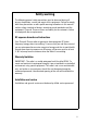
Safety warning 1 The following general safety precautions must be observed during all phases of operation, service and repair of this equipment. Failure to comply with these precautions or with specific warnings elsewhere in this manual violates safety standards of design, manufacture and intended use of the equipment. Thrane & Thrane assumes no liability for the customer's failure to comply with these requirements.
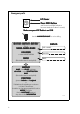
Emergency calls Lif ov er iftt CCov over Press RED Button until acoustic and light-indication becomes steady (more than 3 seconds) Mak adi o is on CCH1 H1 akee sur suree your VHF R Radi adio H166 ROP HONE for voice calling Use the HANDMIC HANDMICR OPHONE MAYDAY-M AYDAY-M AYDAY -MA -MA This is NA ME-NA ME-NA ME NAME-NA ME-NAME-NA ME-NAME CAL ALLLSIGN OWN ID SHIP‘s NAME: CALLSIGN: or other IDENTIFICATION M MSI MMSI: (If the initial alert is sent by DSC) MAYDAY NA ME of the VESSEL in distress NAME CA
Preface 2 Radio for occupational use The SAILOR 6215 VHF DSC fulfils the requirements of the EC directive 1999/5/EC, Radio and Telecommunications Terminal Equipment and is intended for use in maritime environment. SAILOR 6215 VHF DSC is designed for occupational use only and must be operated by licensed personnel only. SAILOR 6215 VHF DSC not intended for use in an uncontrolled environment by general public. SAILOR 6215 VHF DSC is designed for installation by a skilled service person.
vi
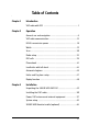
Table of Contents Chapter 1 Introduction VHF radio with DSC ............................................................ 1 Chapter 2 Operation General use and navigation ...............................................6 VHF radio communication .................................................12 HI/LO transmission power ................................................ 18 Watch ................................................................................19 Scan ...........................................
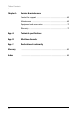
Table of Contents Chapter 4 Service & maintenance Contact for support ...........................................................65 Maintenance ....................................................................65 Equipment and accessories .............................................. 71 Warranty .......................................................................... 71 App. A Technical specifications App. B Maritime channels App. C Declaration of conformity Glossary .........................
11 Chapter 1 1 Introduction Introduction VHF radio with DSC SAILOR 6215 VHF DSC, your new SAILOR VHF radio with full DSC functionality, is approved to R&TTE and is waterproof to the IPx8 and IPx6 standard. As part of the required safety equipment, use the SAILOR 6215 VHF DSC in an emergency situation. However the best way to guarantee functionality in an emergency situation, is to use the radio in daily communication on board. The VHF radio is a simplex/semi duplex VHF radio.
Chapter 1: Introduction Controls on the front plate 2 1 5 6 3 7 8 4 9 10 1. Loudspeaker. 2. Four soft keys with function title in the display. 3. Quick selection key for channel 16 and the programmed preference channel. 4. Large display. 5. Connector for Handmicrophone or handset. 6. Button for sending a DSC Distress alert. 7. Squelch control to mute background noise. 8. Replay button to play back up to 90 s voice message. 9.
1111 Chapter 1: Introduction The picture shows the display after start-up. The display holds various fields of information, depending on the currently selected function. 1 HI/LO 3 WATCH CALL 1. Action line containing information relevant for the currently selected function. Introduction SAILOR 6215 VHF DSC display 2 GPS Position US 16 4 MORE... DISTRESS/CALL 5 2. Current working channel. 3. Functions you can select with the soft keys.
Chapter 1: Introduction 4 VHF radio with DSC
Operation 2 Before using the VHF radio make sure that the VHF antenna, power and other external equipment are connected properly. For instructions see chapter Installation on page 49.
Chapter 2: Operation General use and navigation Power on and speaker volume The VHF radio has a dual-function on/off wheel knob for power on/off and volume control. • To power on the VHF radio press the on/off wheel knob. • To power off the VHF radio, press and hold the on/off wheel knob and follow the instructions in the display. • To adjust the speaker volume, turn the volume wheel knob (clockwise = louder, counter clockwise = softer, until muted).
When the VHF radio is powered on for the first time, you must enter the vessel’s MMSI number. Hereafter the MMSI number is briefly displayed after power up. The MMSI is a unique, 9-digit identifier assigned to your ship. Important The MMSI number must be programmed into the VHF radio to use any DSC functionality. The radio will prompt for the MMSI number at each power-up until the MMSI has been entered. An error message is displayed when trying to initiate any DSC function.
Chapter 2: Operation Once programmed, you can see the MMSI number in the service line directly after start-up. The DSC functionality is operational at any time. The message NO DSC (NO MMSI) is shown in the action line if the MMSI is not programmed. HI/LO WATCH CALL MORE GPS Position 16 INT MMSI NUMBER 219830067 Position and MMSI Information To display position and MMSI information for the SAILOR 6215 VHF DSC radio, do as follows: 1. Press the soft key POS.
Speaker devices The VHF radio can be equipped with the following speaking devices: 2222 Chapter 2: Operation SAILOR 6202 Handmicrophone with a PTT (Push To Talk) button. • Handset with a microphone, ear piece and a PTT button. The volume in the ear piece can be adjusted, for details see Controller setup on page 10. • Loudhailer. • External speaker. Operation • See Controller setup on page 10 for managing speaking devices.
Chapter 2: Operation Soft key Function SCAN Scanning function HAIL Loudhailer FOG Fog horn PBOOK Phone book SETUP Setup pages for RADIO, HAILER/FOG, SYSTEM, CONTROLLER and DSC The functions of the SAILOR 6215 VHF DSC are accessed and set using the four soft keys to the left of the display. The current function of a soft key is shown in 4 soft keys the display next to the soft key. For some applications there are two control levels HI/LO WATCH CALL GPS Position 16 INT MORE...
3. Turn the selector wheel knob to go to a setting, then press the selector wheel knob to change the setting. 4. Press EXIT to return to normal radio operation. Parameter Adjust earpiece volume for handset 1: OFF, 1 to 14 Operation Handset 1 vol: Description 2222 Chapter 2: Operation Note: Default setting is OFF. If a handset is connected to the front connector this value must be configured to a value (1-14).
Chapter 2: Operation VHF radio communication In this section of the manual you find information on • Basic VHF operation • VHF channels • Programming a call channel • Naming a channel Basic VHF operation You can make VHF calls using the Handmicrophone or another speaking device. Note A single, short press on the 16/C key will always bring you to channel 16, the international calling and distress channel, no matter which display the radio showed. Quick guide to radio telephone calls 1.
When you hear your call name in the loudspeaker, proceed as follows: HI/LO GPS Position WATCH 1. An RX symbol shows that the radio is receiving on the working channel displayed. CALL 16 INT MORE...DISTRESS/CALL RX HI/LO GPS Position INT 2. Lift the Handmicrophone or take the handset. 3. Press the PTT key. A TX symbol shows that the radio is transmitting on the working channel displayed. 4. Repeat the name of the station calling you and say: “This is [your ship’s name]”. WATCH CALL 16 MORE...
Chapter 2: Operation 5. Say: “This is [your ship’s name]”. 6. Say: “Over.” and release the PTT key to listen. An RX symbol shows that the radio is receiving on the working channel displayed GPS Position HI/LO WATCH CALL 7. When answered, agree upon a working channel other than 16. 16 MORE...DISTRESS/CALL INT RX 8. Switch to the new channel by turning the selector wheel knob to the agreed channel and begin your conversation.
2222 Chapter 2: Operation VHF channel table Description Weather channels have the prefix W. (For US and CA channels only.) Private (PRIV) Up to 40 user-defined private channels. Contact your dealer for programming private channels. Operation Weather (WX) Programming a call channel To program a call channel (or quick selection), do as follows: 1. Make an extra-long press (2.5 s duration) on the 16/C key. 2. Press the soft key CALL CH. The channel designator is flashing. 3.
Chapter 2: Operation 5. Press the soft key OK to confirm the entered value and to leave edit mode. OK BACK 6. Press EXIT to return to return to the standard VHF display. CLEAR CANCEL PROGRAM 14 INT NEW_ Display for non-VHF applications When the radio is used for functions other than VHF, the display is arranged differently. The large channel display moves to the bottom line along with selected icons.
Engagement status 2222 Chapter 2: Operation • A new channel selected • PTT pressed or, • Voice signal received The engagement state is used to prohibit incoming DSC calls from taking over control of the transmitter channel, disrupting ongoing communication. When the radio is engaged in VHF communication not initiated by DSC, this is indicated with the icon in the lower right position of the display.
Chapter 2: Operation HI/LO transmission power Press the soft key HI/LO to toggle the transmit power between low (1 W) and high (25 W). If LO is not displayed, the transmit power is HI. US channels: Local mode, 10 dB attenuation To attenuate to the incoming signal, do as follows: 1. Press the soft key LOCAL to add 10 dB attenuation. If it is not in the display, press the soft key MORE until LOCAL appears in the display. Note Local mode is automatically exited when using channel 16.
2222 Chapter 2: Operation Watch Dual watch 16 9 Working channel Triple watch 16 9 Operation The SAILOR 6215 VHF DSC radio can be set to dual watch or triple watch. In dual watch, the working channel and channel 16 are watched. In triple watch the working channel, channel 16 and the programmed call channel are watched. 24 Working channel You can select the working + channel 16 + channel 16 + call channel channel in any watch mode by turning the selector wheel knob.
Chapter 2: Operation Scan The radio has a scanning function for tagged channels. Any available channel, including weather and private channels, can be tagged and added to the scanning sequence. As default the radio scans with priority scanning of channel 16. If a signal is received while in any scanning mode, only channel 16 continues to be watched. If there is a signal in one of the scanned channels, the display shows the channel in which the signal is received.
2222 Chapter 2: Operation US channels: Watch alarms for NOAA Weather alerts Note NOAA weather channels are available in the waters of USA and Canada only. Operation You can turn on or off an independent watch alarm for a specific weather channel. To turn on or off an independent NOAA weather alarm do as follows: 1. In the SCAN menu, turn the selector wheel knob to select a specific weather channel. EXIT PRIORITY SCAN SC STOP 2.
Chapter 2: Operation Radio setup In the RADIO SETUP you set scan and watch mode, select the channel table and can set and view the ATIS code. To change a setting in the RADIO SETUP, do as follows: 1. Press the soft key SETUP. If it is not in the display, press the soft key MORE until SETUP appears. 2. Press the arrow soft key or to advance to RADIO SETUP. 3. Turn the selector wheel knob to go to a setting, then press the selector wheel knob to change the setting. 4.
Parameter ON: All channels tagged for scanning are scanned while monitoring channel 16. (default). OFF: Only the channels tagged for scanning are scanned in sequence, not channel 16, unless it is tagged for scanning.
Chapter 2: Operation Parameter ATIS code Description The ATIS code (Automatic Transmitter Identification System) is used for identification to marine coast and inland stations and its use is mandatory in a number of European inland waterways such as e.g. the river Rhine. Like the MMSI number the ATIS number is issued by the relevant authority.
DSC calls • Sending, acknowledgment and cancel own distress • Receiving distress calls • DSC calls for communication • DSC setup Operation In this section of the manual you find information on: 2222 Chapter 2: Operation Sending, acknowledgment and cancel own distress Sending a distress message To send a distress message do as follows: 1. Lift the cover over the red distress button and press and hold the distress button for longer than 3 seconds.
Chapter 2: Operation Having pressed the red distress button and sent the distress message, press the soft key INFO to display further information: • STATION: shows the radio’s MMSI number. • NAT: shows the nature of distress, see also Sending a distress message with specified nature on page 26. PAUSE DISTRESS (DETAIL) STATION: 123456789 ANNUL NAT: UNDESIGNATED LAT: 23°23.3234 N INFO LON: 123°23.
4. Then lift the cover of the red distress button and push the Distress button for 3 seconds. Acknowledgement of own distress When the SAILOR 6215 VHF DSC receives an acknowledgement of distress from another vessel or station, a 2-tone alarm sounds. The display shows the MMSI number of the station who sent the distress acknowledgement call, the status and the time passed since the distress acknowledgement arrived (format: mm:ss). OK OWN DISTRESS DISTRESS ACKNOWL.
Chapter 2: Operation 2. Press the soft key YES to go ahead with the cancelling process. At this stage you have the option to press the soft key NO to return to distress sending procedure. 3. The SAILOR 6215 VHF DSC will send the Selfcancellation call on channel 70 and the display automatically shows the message that you should say when cancelling the distress with a radio message. 4.
When the radio receives a distress call, the 2-tone alarm sounds. Types of distress calls are DISTRESS, DISTRESS ACK, DISTRESS RELAY and DISTR. RELAY ACK. CALL RECEIVED OK 1. To switch off the 2-tone alarm press the soft key SILENT. A press on any other key also switches off the 2-tone alarm. 2. If you decide to stay in the communication loop to receive follow up information, updates etc., press the soft key OK.
Chapter 2: Operation Distress call log As long as you are part of a distress session, i.e. you have not pressed QUIT, you receive distress messages and can track all distress messages for the current distress event. Do as follows: EXIT Received Distress 1/3 2009 -8-12 10 :11 DISTRESS CALL FROM: 219005678 NEXT TO: ALL SHIPS STATION: 219005678 PREV NAT: UNDESIGNATED 1. Press the soft key LOG. If it is not in the display, press the soft key MORE until LOG appears. 2.
2. Press and turn the selector wheel knob to select other call types or set the details for the call: Type: DSC call type • Category Individual Routine (default) or safety calls, calls to a ship or a station Group calls Routine All ship calls Safety (default) or urgency Safety test Test call, check of safety equipment Position Routine position request Operation • 2222 Chapter 2: Operation Press and turn the selector wheel knob to change the suggested VHF channel for following communication.
Chapter 2: Operation Display for a DSC session 1. Head line showing the type of call that initiated the DSC session, see table below for a list of available head lines. 2. Session status line displays the current state of the session: QUIT INDIVIDUAL TX WAIT FOR ACKNOWLEDGE HOLD MMSI: 278888913 ELAPSED TIME 0:12 INFO (ACTIVE ) CHANNEL : 15 MORE LO CH:15 1 2 3 4 5 6 • WAIT FOR ACKNOWLEDGE – You made an individual call to a station and are awaiting a reply to establish connection.
Explanation ALL SHIPS TX/RX You have sent / received an all ships call GROUP TX/RX You have sent / received a group call INDIVIDUAL TX/RX You have either sent a call request to a station to establish contact, or another station has made a call to you to establish contact. The call needs a reply. TEST TX/RX You either have sent a SAFETY TEST call or have received a SAFETY TEST call from another station that needs to be replied. POSITION TX/RX A position request was either sent or received.
Chapter 2: Operation Soft key Radio function UNABLE Constructs a reply to the caller if an individual call is received which is not compatible with the radio modes. SILENT Silences alarms. Any key silences the alarm but this soft key function will do only this. ACK Acknowledges a received call request with the suggested parameters. POS (Own Distress) A shortcut to own position data information.
Detail information for DSC sessions (soft key: INFO) 2222 Chapter 2: Operation A DSC session is updated based on DSC calls received or transmitted. Press the soft key INFO to show the details for the current session.
Chapter 2: Operation Details —other calls Explanation LON Longitude position of station in distress POS UTC Time of position Receiving DSC calls If the radio is IDLE (not engaged in another session) and a DSC call is received the call details are shown on the display.
Handling a background session The equipment is designed with the possibility to control a DSC session simultaneously with a VHF communication session. The sessions can keep track of their session state and the communication channel used. If a DSC session is put on HOLD it is automatically put in the background (VHF communication display appears on the previous communication channel). The soft key is used to toggle between the VHF communication and a DSC session on hold.
Chapter 2: Operation DSC call logs To display a DSC call log in the DSC CALL LOGS, do as follows: 1. Press the soft key SETUP. If it is not in the display, press the soft key MORE until SETUP appears. 2. Press the arrow soft key or to advance to DSC CALL LOGS. 3. Turn the selector wheel knob to go to a setting, then press the selector wheel knob to change the setting. 4. Press EXIT to return to normal radio operation.
4. Press EXIT to return to normal radio operation. DSC setting Position Info Description Available position information. 2222 Chapter 2: Operation Auto-Ack Test Operation Here you can enter position data, see also Position and MMSI Information on page 8. Auto-acknowledgement of test DSC messages OFF - Disabled ON – Enabled (default) Auto-Ack Individual Auto acknowledgement of individually addressed, non distress DSC messages OFF - Disabled (default) ON – Enabled Non-Distr.
Chapter 2: Operation DSC setting Auto-switch Channel Description Enable automatic channel switching on reception of DSC calls with subsequent communication channel information, while the radio is not engaged (for calls other than individual station calls of category distress or urgency). ON (default) OFF - LCK icon indicates that the channel is locked and must be selected manually DSC Self Test You can set the radio to run a DSC self test. OFF: Disabled (default) RUN: Run test.
Phone book 2222 Chapter 2: Operation • Name (up to 20 characters) • Type (SHIP, GROUP or COAST STATION) • MMSI number • Channel • Position Auto Acknowledge (yes or no) or Listen to Group Operation Use the phone book when making a DSC call. You can enter up to 50 contacts. A contact has the following details: The phone book is always sorted alphabetically by contact names. Use the soft key FILTER to toggle between CONTACTS - ALL, COAST, SHIP or GROUP.
Chapter 2: Operation Adding a contact to the phone book To add a contact to the phone book do as follows: 1. Press the soft key PBOOK. If it is not in the display, press the soft key MORE until PBOOK appears in the display. 2. Press the soft key ADD. 3. Press the selector wheel knob to enter the field. Enter the name by turning the selector wheel knob to the desired letter, press the selector wheel knob to accept the letter and advance to the next letter. To finish press the soft key OK. 4.
Editing a contact 2222 Chapter 2: Operation 1. Press the soft key PBOOK. If it is not in the display, press the soft key MORE until PBOOK appears. 3. Press and turn the selector wheel knob to browse through the details of the contact. 4. Continue as described in Adding a contact to the phone book from step 2 onwards. Deleting a contact 1. Press the soft key PBOOK. If it is not in the display, press the soft key MORE until PBOOK appears. 2.
Chapter 2: Operation Loudhailer with talk-back The SAILOR 6215 VHF DSC supports a loudhailer with a talk-back function. Important When the hailer is in talk-back mode and a radio signal is received, the radio signal has a higher priority and is heard in the loudspeaker. To activate the loudhailer do as follows: 1. Press the soft key HAIL. If it is not in the display, press the soft key MORE until HAIL appears. 2. Press PTT on the speaking device to activate the HAILER. 3.
The SAILOR 6215 VHF DSC has an automatic fog horn application with several foghorn patterns. Once started, it runs in the background while running any other application. The fog horn may be combined with the loudhailer talkback mode. When the fog horn is activated, the text FOG is shown in the top right corner of the display. Important Loudhailer talk-back may be active between foghorn emissions. See Hailer and Fog horn setup on page 47.
Chapter 2: Operation 2. Use the selector wheel knob to browse through the patterns available. UNDERWAY 1 long blast every 120 s STOP 2 long blasts every 120 s SAIL 1 long blast followed by 2 short blasts every 120 s TOW 1 long blast followed by 3 short blasts every 120 s AGROUND 3 rings, followed by 5 s constant bell pattern, then 3 rings every 60 s ANCHOR One 5 s bell pattern every 60 s 3. Press the selector wheel knob at the wanted pattern to accept the pattern. 4.
Hailer and Fog horn setup 2222 Chapter 2: Operation 1. Press the soft key SETUP. If it is not in the display, press the soft key MORE until SETUP appears. 2. Press the arrow soft key or to advance to HAILER/FOGHORN SETUP. 3. Turn the selector wheel knob to go to a setting, then press the selector wheel knob to change the setting. 4. Press EXIT to return to normal radio operation. Parameter Settings Hailer Talk back OFF - Talk back is disabled (Default).
Chapter 2: Operation Replay function Replay allows the operator to playback received voice messages in the loudspeaker. Recording is activated automatically when a signal is received. Recording is not possible during playback. Up to 60 tracks or 90 seconds can be handled. The recorded channel is displayed. The message length is shown in seconds. The display shows how old the message is. If the 90 s storage limit is reached, the oldest data is overwritten.
Chapter 3 In this chapter you find information and guidelines for: • Unpacking the SAILOR 6215 VHF DSC • Installing the VHF radio • Power, VHF antenna and external equipment 3333 Installation 3 Installation Unpacking the SAILOR 6215 VHF DSC The following items are included in the delivery of a SAILOR 6215 VHF DSC: • SAILOR 6215 VHF DSC • SAILOR 6202 Handmicrophone with spiral cable • User and installation manual (this manual) • Installation guide • Mounting bracket with two wheel knobs
Chapter 3: Installation Installing the VHF radio You can mount the VHF radio as a desktop, overhead or flush-mounted unit integrated in the instrument panel. Provide space enough to access the front panel connectors and for installing a cradle for the speaking device. Provide at least 120 mm space at the back of the SAILOR 6215 VHF DSC radio to allow free air circulation.
SAILOR 6215 VHF DSC with U mounting bracket The mounting bracket and two knobs are included in the delivery.
Chapter 3: Installation Overhead mounting 52 Installing the VHF radio
Mounting with U mounting bracket To mount the VHF radio as tabletop, do as follows: Installation 1. Find a suitable location for the VHF radio. Check that the space is wide/deep enough to accommodate the VHF radio. 3333 Chapter 3: Installation 2. Fasten the bracket with 4 screws (included in the delivery.) 3. Insert the VHF radio in the bracket and fasten it with the two knobs. 4. The display of the VHF radio should be at an angle of approximately 90° to your line of sight when operating it.
Chapter 3: Installation SAILOR 6215 VHF DSC for flush mount You can mount the VHF radio to a flat surface, e.g. an instrument panel. The flush mount installation kit is included in the delivery. 89mm R2.5mm x 4 177mm Remove material from shaded area only! Important 54 The scaling in the above drawing is not 1:1. Consequently do not attempt to use a print or copy of this page without checking the dimensions.
1. Find a suitable location for the VHF radio. Check that the space is deep enough to accommodate the VHF radio and an additional min. 120 mm space for cable entry. 3333 Chapter 3: Installation 2. Keep free distance to allow free air circulation around the VHF radio and to allow sufficient space for access to cables, see the drawing on this page. 3. Cut out the hole for the VHF radio where you want to mount it. Use the cutting template in the installation guide. 4.
Chapter 3: Installation SAILOR 6202 Handmicrophone Handmicrophone with spiral cable and PTT button.
Power, VHF antenna and external equipment 1. ACC connector 2. CTRL connector for control speaker microphone 1 2 3 4 5 Installation 3. Power, Loudhailer, foghorn and external speaker 3333 Chapter 3: Installation 4. VHF antenna 5. Ground stud ACC connector Use the connector marked ACC to connect GPS input. The interface for GPS is NMEA 0183 (EN61 162-1 Listener / EN61 162-2 Talker). 1 2 3 Connector type: Circular connector, 10pin.
Chapter 3: Installation NMEA interface description U20 4k42 Vcc 500R U24 ACC connector NMEA in+ 464k NMEA inuP NMEA out+ O pin1 O pin2 O pin3 Vcc NMEA out- O pin4 U43 681R O 120R J4 B 681R NMEA Driver A U43 NMEA interface Specifications NMEA input: Impedance: 600 Ohm Max. 2mA at min. level of 2V NMEA output Load Impedance: > 60 Ohm Drive load: < 35 mA The NMEA interface supports NMEA 0183 v2.0, v2.1 and v2.3.
The following sentences are supported: • FSI: All fields are decoded • GGA: UTC, "Position", "quality indicator". All other fields are unused • GLL: UTC, "Position", "Status" and "mode". All other fields are unused • GNS: UTC, "Position" and "mode". All other fields are unused • RMC: UTC, "Position", "Status", "Date" and "mode". All other fields are unused • ZDA: UTC, "Day", "Month", and "Year".
Chapter 3: Installation Power, Loudhailer, foghorn and external speaker Use the connector marked PWR/EXT to connect power, loudhailer and an external speaker. The cable for this connector is part of the delivery. 1. Blue wire: Power 2. Red isolation on inner connector: loudhailer 3. White isolation on inner connector: external speaker 4.
Protection against water ingress Important You must protect the cable connection with rubber vulcanizing tape as shown in the pictures below. This protection prevents water seeping into the VHF radio, cable and connectors. 1 2 3333 Chapter 3: Installation Installation 3 4 VHF antenna Use the connector marked ANT to connect the VHF antenna to the radio with a 50 Ohm coaxial cable with low loss, e.g. RG214. Install a PL259 plug at the cable end.
Chapter 3: Installation Ground stud To ground the radio connect a ground wire from the ground stud of the radio to a suitable grounding point. Use an appropriately sized wire. The ground stud is located above the VHF antenna connector. System setup To change a setting in the SYSTEM SETUP, do as follows: 1. Press the soft key SETUP. If it is not in the display, press the soft key MORE until SETUP appears. 2. Press the arrow soft key or to advance to SYSTEM SETUP. 3.
SYSTEM SETUP Description Inactivity timeout Inactivity time-out to exit functions (e.g. in setup) and return to the application. Range: 1 to 30 minutes, in 1 minute steps Default: 10 min. If you need to change the identity of the radio (MMSI number or ATIS code), contact your local dealer.
Chapter 3: Installation SAILOR 6201 Handset cradle (optional) 75 This Handset has a hook-on/off function, which is activated by a small magnet embedded in the cradle. The cradle must be installed as illustrated in order to ensure the hook-on/off functionality of the Handset. min.
Chapter 4 Contact your authorized dealer for technical service and support of the VHF radio. Before contacting your authorized dealer you can go through the troubleshooting guide to solve some of the most common operational problems. Maintenance 4 Preventive maintenance Maintenance of the SAILOR 6215 VHF DSC radio can be reduced to a maintenance check at each visit of the service staff. Inspect the radio for mechanical damages, salt deposits, corrosion and any foreign material.
Chapter 4: Service & maintenance DSC self test To run a control routine DSC self test, do as follows: 1. Press the soft key SETUP. If it is not in the display, press the soft key MORE until SETUP appears. 2. Press the arrow soft key or to advance to DSC SETUP. 3. Turn the selector wheel knob to select DSC Self Test. Press and turn the selector wheel knob to select RUN. The test will check the ability to encode/decode DSC signalling on RF level.
Chapter 4: Service & maintenance Remedy No communication The loudspeaker is mute. Check the antenna installation. Check antenna cable. Check handset/Handmicrophone and cable. GPS Position requested. If the VHF, despite being connected to a GPS/position source, prompts for entering the position and time information, the automated update has most likely been lost either due to missing data on the line, broken cabling or the GPS/position source has failed.
Chapter 4: Service & maintenance Action Symptom DSC routine testing Remedy Check the DSC function regularly. Verify the complete DSC installation, with antennas, by transmitting a Safety Test call to another station (coast or ship). The test call is generated using the DSC call flow via menu CALL. The call should normally be replied by the receiving station without questioning. The default configuration of a SP6215/16 is autoacknowledgement of any received Safety test call requests.
Chapter 4: Service & maintenance Remedy Radio time DSC logs are sorted with wrong time stamp or radio time is incorrect A wrong radio time indication should occur only if GPS position source is not connected or providing correct time data. A valid GPS time signal will update the UTC time used for time stamping the DSC logs. If a GPS/position source is not connected to the VHF radio and hence position and time is entered manually, you must enter the "radio time" also manually, at least after power up.
Chapter 4: Service & maintenance Action Symptom Device failure Remedy If any of the checks and tests described in this section do not assist in resolving the difficulties experienced in the operation and/or performance of the VHF installation, a fault may have developed in the VHF radio itself.
Chapter 4: Service & maintenance SAILOR 6209 Accessory connection box You can connect the SAILOR 6209 Accessory Connection Box for input from GPS (NMEA) and SAILOR 6201 Handset option. The wire terminal blocks are connected in parallel. Service & maintenance 4444 Equipment and accessories 36090 Warranty For repair or replacement of the VHF radio within terms of warranty, contact your local dealer.
Chapter 4: Service & maintenance 72 Warranty
AAAA Technical specifications A T Item Specification Weight SAILOR 6215 transceiver unit approx. 1.2 kg Weight SAILOR 6215 transceiver unit approx.
Appendix A: Technical specifications Item Specification Number of P channels The radio may be programmed with up to 40 private channels that can be managed in all channel modes. Transmit power Hi/Lo: 25 W and <1 W RF output power 25 W +0 dB / - 1.5 dB 1 W +0 dB / - 1.5 dB Modulation 25 kHz 12.
BBBB Appendix B Maritime channels B Channels 1 2 3 4 5 6 7 8 9 10 11 12 13 14 15 16 17 18 19 20 21 22 23 24 25 26 27 28 TX MHz 156,050 156,100 156,150 156,200 156 250 156,250 156,300 156,350 156,400 156,450 156,500 156,550 156,600 156 600 156,650 156,700 156,750 156,800 156,850 156,900 156,950 157,000 157,050 157,100 157,150 157,200 157,250 157,300 157,350 157,400 RX SIMPLEX MHz Intership Port 160,650 160,700 160,750 160,800 160 850 160,850 156,300 160,950 156,400 156,450 156,500 156,550 156,600 156 6
Appendix B: Maritime channels US channels Channels 1A 2 3 4 5A 6 7A 8 9 10 11 12 13 14 15B 16 17 18A 19A 20 20A 21A 22A 23A 24 25 26 27 28 TX RX SIMPLEX MHz MHz 156,050 156,050 DUPLEX B) B) B) 156,250 156,300 156,350 156,400 156,450 156,500 156,550 156,600 156,650 156,700 156,800 156,850 156,900 156,950 157,000 157,000 157,050 157,100 157,150 157,200 157,250 157,300 157,350 157,400 156,250 156,300 156,350 156,400 156,450 156,500 156,550 156,600 156,650 L) 156,700 RX) 156,750 156,800 Distress and callin
Channels 1 2 3 4 5 6 7 8 9 10 11 12 13 14 15 16 17 18 19 20 21 22 23 24 25 26 27 28 TX MHz 156,050 156,100 156,150 156,200 156,250 156,300 156,350 156,400 156,450 156,500 156,550 156,600 156,650 156,700 156,750 156,800 156,850 156,900 156,950 157,000 157,050 157,100 157,150 157,200 157,250 157,300 157,350 157,400 RX SIMPLEX MHz Intership Port 160,650 160,700 160,750 160,800 160,850 L) 156,300 160,950 L) 156,400 156,450 L) L) 156,500 156,550 L) 156,600 L) 156,650 L) L) 156,700 L) 156,750 L) L) 156,800 Dist
Appendix B: Maritime channels Ca channels Channels 1 2 3 4A 5A 6 7A 8 9 10 11 12 13 14 15 16 17 18A 19A 20 21A 21B 22A 23 24 25 26 27 28 TX MHz 156,050 156,100 156,150 156,200 156,250 156,300 156,350 156,400 156,450 156,500 156,550 156,600 156,650 156,700 156,750 156,800 156,850 156,900 156,950 157,000 157,050 157,100 157,150 157,200 157,250 157,300 157,350 157,400 RX SIMPLEX DUPLEX MHz 160,650 160,700 160,750 156,200 !) 156,250 !) 156,300 156,350 156,400 156,450 156,500 156,550 156,600 156,650 156,700 1
If the radio is used in regions where neither of the four described standard channels are allowed, a reduced channel table with international channel designators and frequencies can be made. Contact your local dealer for programming the alternative channels. Maritime channels Alternative channels BBBB Chapter B: Maritime channels Private channels Up to 40 licensed private channels for non-DSC purposes may be specified. For programming the private channels contact your local dealer.
Chapter B: Maritime channels 80
Appendix C C Declaration of conformity The SAILOR 6215 VHF DSC is certified as stated in the “Declaration of Conformity with R&TTE Directive, enclosed in copy on the next page.
Appendix C: Declaration of conformity Thrane & Thrane A/S Declaration of Conformity with R&TTE Directive The undersigned of this letter declares that the following equipment complies with the specifications of EC directive 1999/5/EC concerning Radio & Telecommunications Terminal Equipment.
Glossary D A AIS Automatic Identification System, used by ships and Vessel Traffic Services (VTS) principally for identification and locating vessels. ATIS Automatic Transmission Identification System D DSC DDDD Glossary Digital Selective Calling G NMEA sentence, essential fix data which provide 3D location and accuracy data.
Glossary U UTC Coordinated Universal Time. The International Atomic Time (TAI) with leap seconds added at irregular intervals to compensate for the Earth’s slowing rotation. Leap seconds are used to allow UTC to closely track UT1, which is mean solar time at the Royal Observatory, Greenwich. V VHF Very High Frequency Z ZDA 84 NMEA sentence, date and time.
Index 16/C, 12 90 s replay, 48 E backlight, 1 dim, 6 Bi, 77 Bi channels, 77 browse channels, 6 A ACC connector, 57 accessories, 71 acknowledgement, distress, 27 action line, display, 3 activate foghorn, 41, 45 scan resume, 22 scanning, 20 watch, 19 ADD, 42 add a contact, 42 adjust squelch, 9 adjusting speaker volume, 6 ALT, 79 ALT channel table, 23 ANT connector, 61 ATIS code, 24 change, 63 attenuation control, 18 Auto-Ack Individual, 39 Auto-Ack Test, 39 Auto-switch Channel, 40 B background sessions D
Index channels Bi, 77 Ca, 78 international, 75 primary, 14 private, 15 US, 76 weather, 15 Comm Inactivity, 39 compass safe distance, 50 connector ACC, 57 ANT, 61 CTRL, 59 external speaker, 60 foghorn, 60 loudhailer, 60 VHF antenna, 61 contact, 65 adding, 42 deleting, 43 editing, 43 controls, front plate, 2 cradle for 6201, installation, 64 CTRL connector, 59 D deactivate, 46 foghorn, 46 watch, 19 default reset, 62 DELETE, 43 delete contact, 43 delivery, items included, 49 dim, 6 display, 3 86 distress a
Index factory defaults, 62 flush mount, 54 FOG, 45 foghorn, 1, 45, 46 activate, 41, 45 connector, 60 patterns, 1 test tone, 46 foghorn frequency, setup, 47 frequency range, VHF, 73 front plate, controls, 2 fuses, how to replace, 70 G GPS input, 57, 71 GPS position display, 8 H HAIL, 44 hand microphone installing, 56 Handmicrophone, 9 handset cradle installation, 64 hang time, 22 headline DSC, 32 HORN, 46 input GPS, 71 handset, 71 NMEA, 62 installation cradle for 6201, 64 desktop, 51 flush mount, 54 hand
Index maritime channels, 75 MAYDAY, iv message replay, 48 MMSI change, 63 MMSI number reviewing, 8 MORE, 10 mounting, 50 flush mount, 54 with mounting bracket, 53 multiple calls, DSC, 37 mut speaker, 9 N NAME, 15 name a call channel, 15 nature of distress, 26 night vision, how to dim, 6 NMEA, 57 NMEA input, 62 NMEA interface, 58 Non-dist Inactivity, 39 Non-distr.
Index Index safety summary, iii salt deposits, 65 scan add channel, 20 hang time, 22 priority, 23 remove channel, 20 resume time, 22 resume, activate, 22 scanning start, 20 selector wheel knob, 2, 6 self test, 66 selt test DSC”, 40 semi duplex, 1 serial number, 62 service line, display, 3 setup controller, 10 DSC, 38 foghorn frequency, 47 Radio, 22 system, 62 watch, 22 simplex, 1 soft key ADD, 42 CALL, 41 DELETE, 43 DSC, 33 FOG, 45 HAIL, 44 HORN, 46 LOCAL, 18 MORE, 10 NAME, 15 OVRIDE, 18 PBOOK, 41 STOP,
Index technical data, 73 temperature operational, 73 storage, 73 testing, foghorn, 46 time out non distress, 39 timeout, 63 Distress, 39 VHF and other non distress, 39 triple watch, 22 change to dual, 19 U US, 76 US channel table, 23 US channels, 76 UseGPS, 8 UTC time, 3 enter manually, 8 V VHF antenna cable, 61 antenna connector, 61 channels, 14 frequency range, 73 volume louder, 6 softer, 6 speaker, 6 Volume wheel knob, 2 W warnings, 65 90 warranty, 71 limitation, iii WATCH, 19, 20 watch dual and tr
TT98-128471-THR-C Thrane & Thrane A/S • info@thrane.com • www.thrane.