Product Tour Getting Started Controller Settings Programming With Smart Technology Software Troubleshooting Technical Support 1 3 5 13 18 18 Français Commencer l’installation Reglages du Controleur Programmer Votre Controleur Section de Depannage Support Technique 20 22 30 35 25 ENGLISH English ENGLISH Table Of Contents Beginn Controller-Einstellungen Programmieren Ihres Pro Flight Controllers Fehlerbehebung Technical Support (Technische Unterstützung) 37 39 47 52 52 ENGLISH Deutsch Guida Introd
1
2 ENGLISH ENGLISH ENGLISH ENGLISH ENGLISH
GETTING STARTED In order for this product to function correctly, please install the drivers on the CD supplied with this product. Drivers and Software installation for users of Windows® XP, 32-and 64-bit A) Drivers Only Installation 1. With your computer switched on, close down any programs that are currently running and insert the Installation CD into your CD-ROM drive. 2. When the Introduction Screen appears, click Install Software to continue.
A) Drivers Only Installation 1. With your computer switched on, close down any programs that are currently running and insert the Installation CD into your CD-ROM drive. ENGLISH Drivers and Software installation for users of Windows® Vista and 7, 32-and 64-bit 2. When the Introduction Screen appears, click Install Software to continue. If the CD does not run automatically, select Start from the Windows® Taskbar, then Run and type D:\Setup.exe and click OK - where D:\ is letter of your CD-ROM drive. 4.
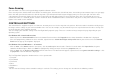
Force Sensing Your new X65F uses force sensing technology to provide ultimate realism.
The test stick tab allows you test all the functions and features of your X65F stick. Buttons / Hats ENGLISH 1. Test Stick To test the X and Y axes simply place your hand on the stick and apply pressure in the forward / back or left / right motions, or a combination of both. You will see the cross hair, as per the image on the left, moving around the square test area; this indicates the X and Y axes are working correctly.
2. Test Throttle The test throttle tab allows you test all the functions and features of your X65F throttle. Buttons / Hats Press any button or use any HAT on your X65F Throttle and the corresponding button or HAT direction will light up on the page; this will indicate that the buttons and HATs are working correctly. Axis The X65F throttle has 4 axes, the Left Throttle, Right Throttle, Rotary 1 and Rotary 2.
The test panel tab allows you test all the functions and features of your X65F Switch Panel. T – Buttons ENGLISH 3. Test Switch Panel Safe Cover / Button Lifting the safe cover will reveal a lit red button. This button is a standard controller button and can be assigned to any in-game function; pressing the button on the switch panel will light the corresponding button in the on-screen image.
4. Force The Force tab allows the changing of the 4 pre-set force settings. When opening the tab you will see 5 main areas, a test area for X, Y and Rudder axes and 4 main adjustment area’s labeled F1 to F4. Test Area Moving the X, Y or Rudder axes will give feedback in the test area. This test area is similar to the test stick page – it can used as a quick reference when adjusting the Force Settings.
5. Deadzones ENGLISH This screen is split into 2 main areas, while you can set the deadzone settings on all 7 axes and 2 mouse axes, you can also adjust the axis envelope on the X, Y and Rudder axes. We will explain both of these features, starting with deadzones. What is a deadzone? ENGLISH A deadzone is a part of the range in which an axis moves that is not detected by the drivers; it has no effect on the game in progress.
Axis Enveloping You will see that the X, Y and Rudder axes have a larger axis box than all the other axis boxes and how they have a diagonal line running through them. The line running from the bottom left to the top right of the box represents the behavior of that axis; for example, if you have the line set as the image on the left, the stick will have the same sensitivity across the whole of the axis range.
From the About screen you can see notes on the programming software, which you may or may not have already installed. ENGLISH ENGLISH ENGLISH ENGLISH You will also see the driver and software version that you have currently installed. ENGLISH 6.
PROGRAMMING YOUR PRO FLIGHT CONTROLLER WITH SMART TECHNOLOGY PROGRAMMING SOFTWARE Introducing Smart Technology Programming Software Smart Technology (ST) Programming Software is the software supplied to configure your controller for enhanced functionality. ST delivers a powerful set of features, allowing you to program your device with the ultimate configuration for total interaction.
ENGLISH On the Main screen you will see a series of tabs along the top, these are: - Product - Settings - Programming - Support Product This screen detects which Pro Flight hardware you have plugged in and shows it on this screen. If you have no Pro Flight hardware plugged in, the Pro Flight Rudder Pedals will appear in the screen. This is because they are first in the list.
Programming From the programming tab, you can mimic your controller to directly copy any of your keyboard commands that are used in your favorite games. The commands are then saved in what we call a Profile. When you click on the programming tab, you will be presented with a high-resolution image of the controller you are going to program on the left, and on the right side of the screen you will see a list of command boxes, called “Cells”, going down the page.
5. We can now test what we have done by opening the “test window”. If you look just above the 3D image there are 7 icons. The 2nd one from the right, which looks like a silver cog, is called Test Profile. Click on this icon and a new window will open. A cursor will already be flashing in the test area, so all we need to do is to press the A button on the X65F. When this is pressed you will see the letter G appear in the window, which proves your first programmed button is working.
Support From the support tab you can access the following features by clicking on them:- Show Tips - Download Drivers and Software - Download Game Profiles - Read ST Programming Manual - Contact Us Show Tips Once clicked, the tip screen will appear on the screen. This is the same screen that appears the very first time you run the ST software – if desired you can run through all tips from this screen.
Q4 My CD is not responding in my CD drive. A 1. Check for any marks or finger prints on the CD, try to wipe with a dry cloth, if there is still no response please use the “Contact Technical Support” section at the bottom of this Q and A. Q5 There is a part of my controller which hasn’t been included in the box. A 1. Please contact the retailer who you have purchased from. Q6 My LEDs are not functioning correctly. A 1. Ensure that the cables are fully plugged in. 2.
If you do not have access to the internet, or if the website cannot answer your question, please contact your local Saitek Technical Support Team. We aim to offer quick, comprehensive and thorough technical support to all our users so, before you call, please make sure you have all the relevant information at hand.
B) Pilotes et Logiciel de programmation pour les utilisateurs avancés 1. Suivez les points 1 à 8 de la procédure d’installation dans la partie A), puis dans la fenêtre Software Setup, sélectionnez Install the SST Programming Software et cliquez sur Next. 2. Dans la fenêtre suivante, cliquez sur Next puis suivez les instructions qui s’affichent à l’écran.
Installation des pilotes et du logiciel pour les utilisateurs de Windows® Vista et 7, 32 et 64 bit A) Installation des pilotes seuls 1. Allumez votre ordinateur, fermez tous les programmes en cours d’exécution et insérez le CD d’installation dans votre lecteur de CD-ROM. 2. Quand l’écran d’Introduction apparait, cliquez sur Install Software pour continuer. Si le CD ne démarre pas automatiquement, cliquez sur Démarrer dans la barre des taches de Windows®, puis Exécuter, tapez D:\Setup.
Pour Windows Vista et Windows 7 – toute version • Cliquez sur Démarrer, sélectionnez Jeux, cliquez sur Outils dans le volet supérieur, puis cliquez sur Périphériques d’entrée dans la liste en dessous de Outils, la fenêtre des Contrôleurs de Jeu s’ouvre, assurez-vous que le X65F est sélectionné en cliquant dessus puis en cliquant sur l’icône Propriétés, ou • Cliquez sur Démarrer, puis cliquez sur Périphériques et imprimantes, l’icône du X65F apparaitra, faites un clic droit dessus puis sélectionnez Game Cont
1. Test Stick L’onglet test Stick vous permet de tester toutes les fonctions et commandes du manche X65F. Boutons / Hats En pressant un bouton ou en utilisant un HAT sur le Joystick X65F, le bouton ou la direction du HAT correspondant s’allumeront sur la page; cela vous indiquera que le bouton ou le HAT fonctionnent correctement. Les Axes Le joystick X65F possède 3 axes, un axe X (gauche et droite), un axe Y (haut et bas) et un axe Rudder (axe de torsion ou de gouverne).
L’onglet test Throttle vous permet de tester toutes les fonctions et commandes de votre manette des gaz X65F. ENGLISH 2. Test Throttle En pressant un bouton ou en utilisant un HAT sur la manette des gaz X65F, le bouton ou la direction du HAT correspondant s’allumeront sur la page; cela vous indiquera que le bouton ou le HAT fonctionne correctement.
Pour tester la roulette, bougez-la vers le haut et le bas sur la manette des gaz; dans la zone de test de la roulette vous verrez la barre verte bouger de haut en bas en fonction du sens dans lequel vous faites tourner la roulette: Cela indique qu’elle fonctionne correctement. 3.
L’onglet Force vous permet de changer les 4 préréglages de force. En ouvrant l(onglet, vous verrez 5 zones principales, une zone de test pour les axes X, Y et Rudder ainsi que 4 zones d’ajustement marquées de F1 à F4. ENGLISH 4. Force ENGLISH Vous verrez les résultats du mouvement des axes X, Y et Rudder dans la zone de test, cette zone de test est similaire à celle de la page Test Stick – elle peut être utilisée comme un point de repère rapide quand vous ajustez les réglages de force.
5. Deadzones Cet onglet comporte 2 zones principales, vous pouvez d’une part régler les paramètres des Deadzone pour les 7 axes et pour les 2 axes de la souris, vous pouvez aussi ajuster l’enveloppe de l’axe sur les axes X, Y et Rudder. Nous allons expliquer ces deux fonctionnalités, en commençant par les Deadzones. Qu’est-ce-qu’une deadzone? Une deadzone est une partie de l’amplitude dans laquelle un axe bouge qui ne peut être détectée par les pilotes et qui donc n’a aucun effet dans le jeu.
You will see that the X, Y and Rudder axes have a larger axis box than all the other axis boxes and how they have a diagonal line running through them. ENGLISH Enveloppement d'un axe ENGLISH Pour bouger la courbe de l’axe, vous n’avez qu’à déplacer la flèche située au dessus des cellules X, Y et Rudder, vous verrez la courbe changer à mesure que vous bougez le curseur.
6. About Dans l’onglet About, vous trouverez des remarques sur le logiciel de programmation que vous l’ayez installé ou pas. Vous verrez aussi les versions des pilotes et du logiciel actuellement installés.
Une fois le logiciel Smart Technology ouvert, une présentation apparaitra, si c’est la première fois que vous lancez le logiciel, une fenêtre « tip » apparaitra, ces fenêtres vous donneront des informations utiles sur le logiciel de profil. Si vous ne souhaitez pas voir ces fenêtres quand vous démarrez le logiciel ST, vous trouverez une case dans le coin de la fenêtre tip que vous pouvez décocher. La fenêtre de tip peut-être fermée en cliquant sur l’icône OK dans le coin inférieur droit.
En haut de l’écran principal, vous trouverez plusieurs onglets que sont : - Product - Settings - Programming - Support Product La page Product est l’écran principal qui s’affiche quand le logiciel Smart Technology est ouvert pour la première fois (voir ci-dessus). Cet écran détecte quel périphérique Pro Flight vous avez connecté et le montre à l’écran, si aucun matériel Pro Flight n’est branché et que le Pro Flight Rudder Pedals apparait, c’est parce qu’il est le premier de la liste.
ENGLISH icone Reload last saved forces qui vous permettra de revenir à la dernière configuration sauvegardée. L’icône Reset to default forces réinitialisera toutes les forces des boutons F1 à F4 et leur redonnera leurs valeurs par défaut.
doit activer, dans cet exemple nous utiliserons la touche G, normalement associée au train d’atterrissage, un grand carreau contenant la lettre G devrait apparaitre dans la cellule comme montré ci-dessous. 4. S’il s’agit de la bonne touche du clavier, presser l’icône de la coche verte à droite. Dans le cas contraire, utilisez la croix rouge et recommencez l’opération afin d’obtenir la commande clavier correcte dans la cellule.
FRANÇAIS ENGLISH ENGLISH Show Tips Après avoir cliqué sur Show Tips, l’écran d’indication apparaitra, il s’agit du même écran que celui qui apparait la première fois que vous lancez le logiciel ST – si vous le souhaitez, vous pouvez consulter toutes les indications depuis cette page. Download Drivers and Software En cliquant sur ce lien, votre navigateur par défaut ouvrira la page de téléchargement des pilotes et des logiciels.
SECTION DE DEPANNAGE Q1-Mon ordinateur ne reconnait pas le contrôleur Pro Flight, que se passe-t-il? R 1 Avez-vous installé les pilotes contenus dans le CD fourni avec ce produit ? R 2 Vérifiez les branchements. Débranchez votre contrôleur et rebranchez le, assurez-vous qu’il est bien enfoncé. R 3 Avez-vous testé votre controleur? Veuillez consulter la section « Réglages du contrôleur » de ce manuel pour plus d’informations.
ENGLISH Technique vous fournira toutes les informations nécessaires pour tirer le maximum de votre produit et pour résoudre les problèmes que vous pourriez rencontrer. Si vous n’avez pas accès à Internet, ou si le site internet ne peut répondre à votre question, veuillez contacter votre service local de Support Technique Saitek.
Beginn Damit dieses Produkt ordnungsgemäß funktioniert, müssen die Treiber von der mitgelieferten CD installiert werden. Treiber- und Software-Installation für Benutzer von Windows® XP, 32 und 64 bit A) Nur Treiber-Installation 1. Schließen Sie bei eingeschaltetem Computer alle momentan geöffneten Programme und legen Sie die Installations-CD in Ihr CD-ROM-Laufwerk ein. 2. Wenn der Start-Bildschirm erscheint, klicken Sie zum Fortfahren auf Install Software.
Force Sensing Ihr neues X65F verwendet Force Sensing-Technologie, um ein höchstmögliches Maß an Realismus zu vermitteln. Force Sensing bedeutet, dass der Stick keine beweglichen Teile enthält, dass sich der Stick also auch nicht bewegt. Stattdessen reagiert er auf Druck. Je größeren Druck Sie mit Ihrer Hand auf den Stick ausüben, desto stärker reagiert er. Wenn Sie also stark links neigen wollen, erhöhen Sie den Druck auf die rechte Seite des Sticks.
Wenn Sie die Nase des Flugzeugs leicht anheben möchten, üben Sie einen leichten Druck auf die Vorderseite des Sticks aus. Die Druckrichtungen sind dieselben wie bei einem konventionellen Joystick, diese Methode wird Ihnen also in kürzester Zeit zur zweiten Natur werden. Und Sie werden erkennen, weshalb einige der bekanntesten Kämpfer der Welt diese Methode verwenden. CONTROLLER-EINSTELLUNGEN Ihr Saitek X65F wird gebrauchsfertig ausgeliefert.
Unter dem Reiter “Stick testen” können Sie alle Funktionen und Features Ihres X65F Sticks testen. Knöpfe / HATs ENGLISH 1. Stick testen Um die X- und Y-Achsen zu testen, legen Sie einfach Ihre Hand an den Stick und drücken ihn vorwärts / rückwärts oder links / rechts bzw. eine Kombination aus beidem. Das Kreuz (wie unten im Bild) bewegt sich innerhalb der quadratischen Testfläche. Dies bedeutet, dass X- und Y-Achse korrekt funktionieren.
2. Schubhebel testen Unter dem Reiter “Schubhebel testen” können Sie alle Funktionen und Features Ihrer X65F Schubhebel-Einheit testen. Knöpfe / HATs Wenn Sie an Ihrer X65F Schubhebel-Einheit einen Knopf oder HAT betätigen, leuchtet dieser bzw. die entsprechende HAT-Richtung im Fenster auf. Dies bedeutet, dass Knöpfe und HATs korrekt funktionieren. Achsen Die X65F Schubhebel-Einheit hat vier Achsen. Linker Schubhebel, rechter Schubhebel, Rotary 1 und Rotary 2.
Unter dem Reiter “Schaltpult testen” können Sie alle Funktionen und Features Ihres X65F Schaltpults testen. T-Schalter ENGLISH 3. Schaltpult testen Safe Cover / Knopf Beim Abnehmen des Safe Covers kommt ein beleuchteter roter Knopf zum Vorschein. Hierbei handelt es sich um einen Standard-Controller-Knopf, der jeder Funktion im Spiel zugewiesen werden kann. Beim Drücken des Knopfs auf dem Schaltpult leuchtet der entsprechende Knopf im Kontrollfenster auf.
4. Force Unter dem Reiter “Force” können Sie die Einstellungen der vier voreingestellten Force-Schalter ändern. Wenn Sie die Registerkarte öffnen, sehen Sie fünf Hauptbereiche: einen Testbereich für X-, Y- und Ruder-Achse, sowie vier Einstellungsbereiche mit den Bezeichnungen F1 bis F4. Testbereich Bewegungen der X-, Y- und Ruder-Achse werden im Testbereich angezeigt. Dieser Testbereich ähnelt jenem auf der “Stick testen”-Seite.
Dieser Bildschirm ist in zwei Hauptbereiche unterteilt. Sie können hier sowohl die Totzonen-Einstellungen für alle sieben Achsen und die beiden Mausachsen vornehmen, als auch die Achsen-Kurve für X-, Y- und Ruder-Achse angleichen. Diese beiden Features werden im Folgenden erklärt. Beginnen wir mit den Totzonen. ENGLISH 5. Totzonen DEUTSCH Eine Totzone ist ein Bereich, innerhalb dessen die Bewegung einer Achse von den Treibern nicht erkannt wird, und somit keine Auswirkung auf das laufende Spiel hat.
Sie können bestehende Totzonen einer Achse löschen, indem Sie innerhalb der entsprechenden weißen Box rechtsklicken und Clear Deadzone auswählen. Achsen-Kurve Die X-, Y- und die Ruder-Achse haben eine größere weiße Box als die anderen Achsen, durch die zusätzlich noch eine diagonale Linie verläuft. Die Linie, die von links unten nach rechts oben verläuft, zeigt das Verhalten der jeweiligen Achse.
Hier finden Sie Informationen zur Programmierungs-Software, die Sie eventuell schon installiert haben. ENGLISH ENGLISH DEUTSCH ENGLISH Außerdem sehen Sie, welche Treiber- und Software-Versionen derzeit installiert sind. ENGLISH 6.
PROGRAMMIEREN IHRES PRO FLIGHT CONTROLLERS MIT DER SMART TECHNOLOGY PROGRAMMIERUNGS-SOFTWARE Die Smart Technology Programmierungs-Software Die Smart Technology Programmierungs-Software (ST) ist ein Programm, mit dem Sie Ihren Controller mit erweiterten Funktionen konfigurieren können.
Product (Produkt) Product (Produkt) Die Produktseite ist der Hauptbildschirm, der erscheint, wenn die Smart Technology- Software erstmals geöffnet wird (wie oben gezeigt). ENGLISH - Support (Unterstützung) Unten in der Mitte der Seite befindet sich eine Drop Down-Box. Hier können Sie den Controller aufrufen, dessen Einstellungen Sie ändern oder programmieren möchten. Settings (Einstellungen) ENGLISH Diese Funktion erkennt die angeschlossene Pro Flight-Hardware und zeigt sie auf dem Bildschirm an.
Wenn Sie den Reiter “Programmierung” anwählen, sehen Sie links ein hochauflösendes Bild des zu programmierenden Controllers und rechts eine Liste mit Kommando-Boxen (“Cells”). Was ist ein Profil? Ein Profil ist eine Datei, die programmierte Controller-Kommandos enthält. Wenn Sie z.B. einen Joystick mit mehreren Knöpfen oder HATs haben, können Sie Kommandos, die Sie normalerweise über ein Tastaturkürzel aufrufen müssten, diesen Schaltern zuordnen. Wenn Sie z.B.
Klicken auf dieses Icon öffnet ein neues Fenster. Im Testbereich blinkt bereits ein Cursor. Sie müssen also nur noch den A-Knopf am X65F drücken. Sobald Sie dies tun, erscheint der Buchstabe “g” im Testfenster. Das bedeutet, dass die Programmierung korrekt durchgeführt wurde. ENGLISH 5. Sie können die neu programmierte Funktion testen, indem Sie das “Testfenster” öffnen. Direkt über dem 3D-Bild befinden sich sieben Icons.
Show Tips (Tipps anzeigen) Durch Klicken wird das Tipp-Fenster geöffnet – dasselbe Fenster, das sich öffnet, wenn Sie die ST-Software zum ersten Mal starten. Wenn Sie möchten, können Sie sich von diesem Fenster aus durch alle Tipps klicken. Download Drivers and Software (Treiber und Software herunterladen) Durch Klicken dieses Links öffnet sich Ihr Standard-Browser und verbindet Sie direkt mit der Download-Seite für Treiber und Software.
F7 Meine Achsen scheinen nicht zentriert zu sein oder bewegen sich ungleichmäßig. A 1. Schauen Sie bitte auf der FAQ-Seite nach. Diese ist Teil der Support-Seite auf der Saitek-Webseite. Hier finden Sie einfache Anleitungen, wie Sie die Kalibrierung zurücksetzen können. Die Adressen finden Sie im Abschnitt “Technical Support” in dieser Anleitung.
verursachen. Es wird jedoch keinerlei Garantie dafür übernommen, dass solche Störungen bei einer bestimmten Installation nicht auftreten.
B) Driver e Software di Programmazione per Utenti Avanzati 1. Seguire i punti da 1 a 8 della procedura d'installazione di cui al punto A): nella schermata Installazione software, selezionare Installa il software SST e cliccare Avanti. 2. Nella successiva schermata di Installazione software, cliccare Avanti e seguire le istruzioni.
Installazione del Software e dei driver per utenti Windows® Vista e Windows® 7, a 32 e 64 bit A) Installazione dei soli driver 1. Con il computer in funzione, chiudere tutti i programmi aperti ed inserire nel lettore il CD di installazione. 2. Quando viene visualizzata la schermata introduttiva, cliccare Installa Software per continuare. Se il CD non si avvia automaticamente, dalla Barra delle applicazioni di Windows® selezionare Avvio, poi Esegui, digitare D:\Setup.
Per le versioni di Windows XP a 32 e 64 bit: • nel Pannello di Controllo cliccare due volte l'icona Controller di gioco e poi cliccare Proprietà nella finestra Controller di gioco visualizzata. • Se è già stato installato il software di programmazione SST, nella barra delle applicazioni cliccare col tasto destro sull'icona 'Saitek X65F Flight Stick profiler' e selezionare Pannello di Controllo dall'elenco a scomparsa delle opzioni.
1. Test Stick La scheda 'test stick' consente di verificare tutte le funzioni e le caratteristiche dello stick X65F. Pulsanti / Interruttori HAT Premere qualsiasi pulsante o utilizzare qualsiasi HAT dello stick X65F: la luce corrispondente al pulsante o alla direzione dello HAT si illuminerà. Ciò indica il corretto funzionamento dei pulsanti e degli HAT. Assi Lo stick X65F ha 3 assi: un asse X (Sinistra/Destra), un asse Y (Alto/Basso) ed un asse di Torsione o di Timone (Twist Stick).
La scheda 'test manette' consente di verificare tutte le funzioni e le caratteristiche delle manette di X65F. Pulsanti / Interruttori HAT ENGLISH 2. Test Manette Per verificare le manette sinistra e destra, muovere insieme le manette abbinate oppure separatamente.
3. Interruttori Pannello di Test La scheda 'pannello di test' consente di verificare tutte le funzioni e le caratteristiche del pannello di X65F. Pulsanti T I pulsanti T, da 1 a 4, sono semplicemente pulsanti standard del controller; premendo uno qualsiasi dei pulsanti del pannello interruttori si illuminerà il pulsante corrispondente dell'immagine sullo schermo.
La scheda Forza consente di modificare le quattro impostazioni di forza predefinite. ENGLISH 4. Forza Aprendo la scheda si vedono cinque aree principali: una di test per gli assi X, Y e di Timone e quattro aree principali di regolazione denominate F1, F2, F3 e F4. Spostando gli assi X, Y e di Timone si invia un feedback all'area di test; questa è simile all'area di test dello stick. Può essere utilizzata come guida rapida di riferimento per regolare le impostazioni di Forza.
5. Zone morte Questa schermata è divisa in due aree principali: è possibile impostare le zone morte su tutti i 7 assi e i 2 assi del mouse e regolare l'inviluppo dell'asse X, Y e asse del timone. Saranno spiegate entrambe le caratteristiche a partire dalle zone morte. Che cos'è una zona morta? Una zona morta è una parte del campo di utilizzo di un asse che non è rilevata dai piloti e non ha quindi alcun effetto sul gioco. Può essere intorno al punto centrale del campo dell'asse oppure all'estremità.
Nell'esempio in alto a sinistra, la linea con la parte centrale piana indica che lo stick è più sensibile dove la curva è più accentuata, a ciascuna estremità del campo dell'asse, e meno sensibile dove la linea è piana, intorno al punto centrale. L'esempio in alto a destra indica invece che l'asse X è molto sensibile intorno al punto centrale e meno sensibile alle estremità del campo.
6. Informazioni Sulla schermata informazioni è possibile visualizzare note sul software di programmazione, installato o meno. Vengono visualizzati anche il driver e la versione del software attualmente installati.
Una volta avviato Smart Technology, se si esegue il software per la prima volta, verranno visualizzate delle schermate di "suggerimenti" contenenti utili informazioni. Se, quando si avvia Smart Technology, non si desidera visualizzare tali schermate, deselezionare la casellina nell'angolo della prima schermata "Suggerimenti". La casella dei suggerimenti può essere chiusa cliccando sull'icona OK nell'angolo in basso a destra.
Prodotto La pagina Prodotto è quella della schermata principale quando si apre per la prima volta Smart Technology (vedi sopra). Il sistema rileva il tipo di hardware Pro Flight collegato e lo evidenzia sullo schermo; se non è stato collegato alcun dispositivo verrà evidenziato Pro Flight Rudder Pedals (pedaliera) in quanto primo nell'elenco. In fondo alla pagina, al centro, è presente un menù a tendina che consente di modificare le impostazioni o la programmazione del controller.
Dalla scheda di programmazione è possibile simulare il controller per copiare direttamente i comandi da tastiera utilizzati nel gioco. I comandi vengono memorizzati in Profilo. Quando si clicca sulla scheda di programmazione viene visualizzata un'immagine ad alta risoluzione del controller che si intende programmare; lungo i lati destro e sinistro dello schermo è presente un elenco ‘Celle’ (command boxes). ENGLISH Programmazione 1.
comando. Per questo esempio, digitare Carrello d'atterraggio e premere Enter. La cella verrà completata: pulsante A = carrello d'atterraggio corrispondente al tasto G (immagine seguente a destra). 5. E' possibile ora verificare quanto fatto aprendo la 'schermata di test'. Sopra l'immagine in 3D sono presenti 7 icone; la seconda da destra, simile ad una rotellina dentata, è chiamata 'test profilo'.
Dalla scheda supporto è possibile accedere, cliccandoci sopra, alle seguenti funzioni: - Mostra suggerimenti - Scarica Driver e Software - Scarica Profili di Gioco - Leggi il Manuale di Programmazione ST - Contatti ENGLISH Supporto Scarica Profili di Gioco Cliccando questo collegamento si apre, con il browser predefinito, il collegamento alla pagina Web relativa al download dei profili di gioco. In questa pagina scegliere il controller per visualizzare un elenco di profili adatti ai giochi più recenti.
RISOLUZIONE DEI PROBLEMI D: il mio computer non riconosce il controller Pro Flight, qual'è il problema? R.1: sono stati installati i driver presenti sul CD fornito col prodotto? R.2: controllare i collegamenti dei cavi. Scollegare e ricollegare alla rete elettrica il controller assicurandosi che la spina sia ben inserita nella presa. R.3: è stato eseguito il test del controller? Per ulteriori informazioni fare riferimento alla sezione 'Impostazioni del Controller' di questo manuale . D.
Non riuscite a far funzionare il joystick? Nessun problema, siamo qui per aiutarvi! Quasi tutti i prodotti che ci vengono rispediti perché difettosi non lo sono affatto: semplicemente, non sono stati installati correttamente. Se si riscontrano problemi con questo prodotto, si prega di visitare prima il nostro sito all'indirizzo www.saitek.com. La sezione relativa all'Assistenza Tecnica fornisce tutte le informazioni necessarie per risolvere qualsiasi problema relativo al prodotto.
COMENZANDO Para que este producto funcione adecuadamente, por favor instale los drivers del CD provisto con este producto. Instalación de drivers y software para usuarios de Windows® XP, 32 y 64 bit A) Instalando únicamente los drivers. 1. Con su ordenador encendido, cierre todos los programas que estén en funcionamiento e inserte el CD de instalación en su lectora de CD-ROM. 2. Cuando aparezca la Pantalla de Presentación, presione sobre Instalar Software para continuar.
Detección de Fuerza Su nuevo X65F utiliza tecnología de detección de fuerza para proveerle de un realismo sin igual. Detección de fuerza significa que la palanca X65F no posee partes móviles, por lo que no se moverá; en lugar de ello cuanta mayor presión haga con 72 ENGLISH ENGLISH ENGLISH B) Drivers y Software de programación para usuarios avanzados 1. Siga los pasos 1 a 8 del procedimiento de instalación A.
su mano mayor será la respuesta de la palanca. Por lo tanto, si quiere dirigirla fuertemente hacia la izquierda, deberá aplicar mayor presión a su derecha; subsecuentemente, si quiere subir levemente la nariz de su aeroplano, deberá presionar suavemente en el frente de la palanca. La dirección de la presión será igual a la de los joysticks y palancas convencionales, por lo que este método le será sumamente natural, y comprenderá en poco tiempo por qué algunos de los mejores a del mundo lo utilizan.
La pestaña de prueba de la palanca le permite verificar el funcionamiento y las características de su palanca X65F. Botones / HATs ENGLISH 1. Probar palanca Para probar los ejes X e Y, simplemente coloque su mano sobre la palanca y aplique presión hacia delante / hacia atrás o hacia la izquierda / derecha, o una combinación de ambos. Verá que la cruz se mueve, como se muestra en la imagen siguiente, dentro del cuadro de prueba; esto indica que los ejes X e Y funcionan correctamente.
2. Probar Acelerador La pestaña de prueba del acelerador le permite probar todas las funciones y características de aceleración de su X65F. Botones/HATs Presionando sobre cualquier botón o utilizando cualquier HAT en su acelerador X65F, verá que el botón o HAT correspondiente se resaltará en la página; esto le indicará que los botones y HATs funcionan correctamente. Ejes El acelerador X65F posee 4 ejes; Acelerador Izquierdo, Acelerador Derecho, Rotativo 1 y Rotativo 2.
La pestaña de prueba del panel le permite verificar todas las funciones y características de su panel de interruptores X65F. Botones T ENGLISH 3. Probar Panel Cubierta protectora / Botón Si levanta la cubierta protectora (Safe) verá un botón rojo encendido, este es un botón convencional y puede ser asignado a cualquier función del juego. Si presiona el botón, en el panel de interruptores se iluminará el sector correspondiente al botón, en la imagen en pantalla.
4. Fuerza La pestaña de fuerza permite la modificación de las cuatro configuraciones de fuerzas pre establecidas. Al abrir la pestaña verá 5 áreas principales, un área de prueba para los ejes X, Y, y de Giro, y 4 ajustes principales etiquetados como F1 a F4. Área de Prueba Al mover los ejes X, Y y de Giro se reflejará la acción en el área de prueba; esta área de prueba es similar a la de la página de Prueba de la Palanca – puede ser usada como referencia rápida en el ajuste de la Configuración de Fuerza.
5. Zonas inactivas ENGLISH La pantalla se divide en dos áreas principales, en las que puede establecer la configuración de zonas inactivas en los 7 ejes y en los dos ejes del mouse, y también podrá ajustar la ponderación del eje en los ejes X, Y y de Giro. Explicaremos ambas características, comenzando por las zonas inactivas.
Ponderación de ejes Podrá ver que los ejes X, Y y de Giro tienen un rectángulo de ejes más grande que todos los otros rectángulos, y que tienen una línea diagonal que la atraviesa. La línea, que corre desde la esquina inferior izquierda hasta la esquina superior derecha del rectángulo representa el comportamiento de este eje; por ejemplo, si la línea ha sido establecida como en la imagen de arriba, la palanca se mantendrá en la misma sensibilidad a lo largo de todo el rango de la actividad del eje.
En la pantalla Acerca de podrá ver notas sobre el software de programación, que puede o no haber instalado. ESPAÑOL ENGLISH ENGLISH ENGLISH También verá las versiones de driver y software que tiene instaladas actualmente. ENGLISH 6.
PROGRAMANDO SU CONTROLADOR PRO FLIGHT CON EL SOFTWARE DE PROGRAMACIÓN DE TECNOLOGÍA INTELIGENTE Introduciendo el Software de Programación de Tecnología Inteligente El Software de Programación de Tecnología Inteligente (ST) es el software provisto para configurar su controlador para una mejor funcionalidad. ST le brinda un poderoso conjunto de características, permitiéndole programar su dispositivo con las mejores configuraciones para lograr una interacción total.
ENGLISH En la pantalla principal verá una serie de enlaces en la parte superior, estos son: - Producto (Product) - Configuraciones (Settings) - Programación (Programming) - Soporte (Support) La página de producto es la pantalla principal que aparece cuando el software de tecnología inteligente es abierto por primera vez (como se ve arriba). Esta pantalla detecta el hardware de Pro Flight que ha conectado y lo exhibe en pantalla.
Una vez que las configuraciones de fuerza hayan sido verificadas y establecidas a los niveles deseados, haga clic sobre el botón Guardar Fuerzas (Save Forces) ubicado por debajo de los deslizadores. También verá un botón de Recargar las últimas fuerzas guardadas (Reload last saved forces), que podrá usar en caso de que haya hecho cambios en las fuerzas y no le hayan gustado, esto revertirá sus configuración a la anterior.
5. Ahora podemos probar lo que hemos hecho abriendo la "ventana de prueba" (test window). Si usted mira encima de la imagen 3D, hay 7 iconos, el segundo desde la derecha, que se parece a una rueda dentada, es llamado el perfil de prueba. ENGLISH 4. Si es el comando del teclado deseado, pulse el icono de verificación verde a la derecha. De lo contrario presione sobre la cruz roja y siga nuevamente el procedimiento para obtener el comando del teclado en la celda.
Soporte (Support) Desde la pestaña de soporte se puede acceder a los siguientes recursos haciendo clic sobre ellos: - Mostrar Consejos (Show Tips) - Descargar controladores y software (Download Drivers and Software) - Descargar Perfiles de Juegos (Download Game Profiles) - Leer el Manual de Programación ST (Read ST Programming Manual) - Contáctenos (Contact Us) Mostrar Consejos (Show Tips) Al hacer clic aquí, aparecerá la pantalla de consejos, esta es la misma que aparece la primera vez que ejecuta el soft
Pregunta 3: Uno de los botones o ejes no funciona en mi controlador. Respuesta 1: Por favor, pruebe su producto en el Panel de Control -> Dispositivos de Juego como se menciona en la primera parte de este manual. Respuesta 2: Si sigue experimentando problemas con el controlador, por favor visite en el sitio web de Saitek la página de preguntas más frecuentes de la sección de soporte técnico. Pregunta 4: Mi CD no responde en mi lectora de CD Respuesta 1.
Soporte técnico ¿No puede hacer que su joystick funcione?, no se preocupe, ¡nosotros estamos aquí para ayudarle! Casi todos los productos que nos son retornados como defectuosos no lo son en absoluto - no han sido instalados correctamente. Si experimenta alguna dificultad con este producto, primero visite nuestro sitio Web www.saitek.com.
Conditions de garantie 1 La p.riode de garantie est de deux ans . compter de la date d’achat, avec soumission d’une preuve d’achat. 2 Les instructions de fonctionnement doivent ?tre correctement suivies. 3 Le produit ne doit pas avoir .t. endommag. par une d.gradation, une utilisation non conforme, une n.gligence, un accident, une destruction ou une alt.ration du num.ro de s.rie, l’utilisation de voltages ou courants .lectriques inadapt.s, la r.
ce manuel. Cette garantie agit en lieu et place de toutes les autres garanties, obligations et responsabilit.s. TOUTES GARANTIES, OBLIGATIONS OU RESPONSABILITES IMPLICITES, INCLUANT SANS RESTRICTION LES GARANTIES ET CONDITIONS IMPLICITES DE QUALITE OU D’ADAPTABILITE A UN USAGE SPECIFIQUE, SONT LIMITEES, EN DUREE, A LA DUREE DE CETTE GARANTIE LIMITEE ECRITE. Certains Etats n’autorisent pas de restrictions de dur.e de la garantie, auquel cas les restrictions d.
ENGLISH 4 Gli obblighi di Mad Catz saranno limitati alla riparazione o sostituzione con la stessa unit. o con un’unit. simile, a scelta di Mad Catz. Per ottenere le riparazioni ai sensi della presente garanzia, presentare il prodotto e la prova d’acquisto (ad es. la ricevuta o la fattura) al Centro Assistenza Tecnica Mad Catz (elencato nel foglio separato contenuto nella confezione di questo prodotto), con le spese di trasporto prepagate.
INCUMPLIENTO DE ESTA O CUALESQUEIRA OTRAS GARANTêAS, EXPLêCITAS O IMPLêCITAS Y DE LA NATURALEZA QUE FUESEN. Algunos estados no permiten la exclusi.n o limitaci.n de da.os especiales, incidentales o indirectos, as. que la limitaci.n anterior podr.a no aplicarse a usted. Esta garant.a le da derechos legales espec.ficos y tambi.n podr.a tener otros derechos, que var.an entre estados.