Saito™ 4-Stroke Gasoline Engines Owner’s Operating Instruction Manual Model FG-14C, FG-17 & FG-21 Model FG-30B, FG-36B & FG-40 Version 2012
NOTICE All instructions, warranties and other collateral documents are subject to change at the sole discretion of Horizon Hobby, Inc. For up-to-date product literature, visit horizonhobby.com and click on the support tab for this product.
Model engines produce a substantial amount of power and can create unsafe situations if not used correctly. Always use common sense and observe all safety precautions when operating, handling or performing any procedure involving your engine. Failure to follow safety precautions could result in serious injury and property damage. • Never return unused fuel from the fuel tank back into the fuel container. • Never attempt to repair or modify a propeller beyond its intended use.
Table of Contents Safety Warnings and Precautions . . . . . . . . . . . . . . . . . . . . . . . . . . . . . . . . . . . . . . . . . . . . . . . . . . . . . . . . . . . 2 Introduction to the Saito Gasoline 4-Stroke Engines. . . . . . . . . . . . . . . . . . . . . . . . . . . . . . . . . . . . . . . . . . . . . . 4 Components . . . . . . . . . . . . . . . . . . . . . . . . . . . . . . . . . . . . . . . . . . . . . . . . . . . . . . . . . . . . . . . . . . . . . . . . . .
Components FG-30B FG-36B FG-40 Engine FG-14C 3 FG-17 3 FG-21 3 3 3 3 Valve Adjusting Tools 3 3 3 3 3 3 Muffler Wrench 3 3 3 Ignition SAIG14C153 SAIG17153 SAIG17153 SAIG30B153 SAIG30B153 SAIG40153 Engine Mount SAIG1495 SAI10095 SAIG2095 SAIG3095/ SAIG3695 SAIG3095/ SAIG3695 SAIG3695 Spark Plug 1/4-32; SAIG20120 1/4-32; SAIG20120 1/4-32; SAIG20120 CM-6; SAIG36120 CM-6; SAIG36120 CM-6; SAIG36120 Muffler SAIG1474 SAIG1474 SAIG2074 SAIG3674 SAIG3674 SAIG3674 Muffl
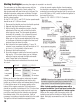
Figure 1 When you attach the muffler, use a drop of oil on the threads to ease the assembly. Screw the exhaust manifold into the engine exhaust port and the muffler as far as the thread will allow (see above drawing). Notice the use of the two wrenches used in tightening the two nuts on the muffler/manifold connection. Use of threadlock is recommended. Remember to ensure cooling air passes by the engine and muffler in a cowled environment.
Fuel • M ix a ratio of gasoline to oil of 20:1 for break-in and continuous operation on all engines. • A mixture of high-quality 91 octane unleaded gasoline and a reliable, high-quality 100% synthetic oil for 2-cycle engines must be used. We recommend Evolution Oil (EVOX1001Q). With the use of an oil mixture of 20:1, it is normal to see a slight amount of carbon buildup on the exhaust valve itself.
Ignition System Saito gasoline four-stroke engines come with the Saito ignition system, composed of the ignition unit, a cord for the sensor (black and white), insulated plug cap, and cord (black and red) for connection to a battery (not included). You will also need to secure an on/off switch (safety switch system). The switch must carry a rating of 3 amps. Be sure to mount the ignition system in a location near the engine and away from the receiver to prevent any unwanted interference.
Preparation Before Starting the Engine (prior to break-in) • M ount the engine on a strong, flat test bench or on the aircraft (in either case, the engine should be secured so it is immobile). • Check to make sure the carburetor will open and close completely. • Check the wiring of the ignition system to make sure it is connected correctly and securely. • Make sure the fuel line is connected securely to the carburetor. • For break-in, use a fuel/oil mix ratio of 20:1.
Starting the Engine (assuming the engine is mounted in an aircraft) The carburetor on the Saito engine comes with the low-speed needle adjusted to a basic setting. The high-speed needle will need to be set by the user. The standard carburetor settings are as follows: The highspeed needle valve is set open counterclockwise from the fully closed position. On the FG-14C, FG-17 and FG-21 the low-speed needle should be set at 7-5/8 from closed. 1. Disconnect the throttle arm from the throttle pushrod. 2.
Be sure to have a helper hold the model securely. • Turn on the transmitter first, then the receiver and check the operation of the throttle servo and other controls. • Turn on the power to the ignition system. • Using an electric starter, begin cranking the engine. It should fire within seconds of applying the starter. Allow the engine to idle for 30 to 45 seconds.
Normal Operation, Maintenance and Additional Information • B e sure to do a range check before flying your model. It would be wise to do the range check with the engine running and without it running. As a simple noise check, after the engine is started, do the normal range check your radio manufacturer recommends. • Be sure to charge the ignition battery and radio system battery before the first flight of the day.
6. Once this change made to the low end, open the high end by 1/2 turn from where you ran it before. Restart the engine and reset the high-end needle valve. 7. With the engine running and the high-speed needle valve set as above, adjust your throttle setting to achieve the desired idle speed. Tip: The more your prop weighs, the lower your achievable idle speed will be. 8. Check the transition of the engine from low-speed to high-speed.
Figure 1 FG-30B/FG-36B/FG-40 = 19mm wrench When you attach the muffler, use a drop of oil on the threads to ease the assembly. Screw the exhaust manifold into the engine exhaust port and the muffler as far as the thread will allow (see above drawing). Notice the use of the two wrenches used in tightening the two nuts on the muffler/manifold connection. Use of threadlock is recommended. Remember to ensure cooling air passes by the engine and muffler in a cowled environment.
Fuel • M ix a ratio of gasoline to oil of 20:1 for break-in and continuous operation on all engines. • A mixture of high-quality 91 octane unleaded gasoline and a reliable, high-quality 100% synthetic oil for 2-cycle engines must be used. We recommend Evolution Oil (EVOX1001Q). With the use of an oil mixture of 20:1, it is normal to see a slight amount of carbon buildup on the exhaust valve itself.
Ignition System Saito gasoline four-stroke engines come with the Saito ignition system, composed of the ignition unit, a cord for the sensor (black and white), insulated plug cap, and cord (black and red) for connection to a battery (not included). You will also need to secure an on/off switch (safety switch system). The switch must carry a rating of 3 amps. Be sure to mount the ignition system in a location near the engine and away from the receiver to prevent any unwanted interference.
Preparation Before Starting the Engine (prior to break-in) • M ount the engine on a strong, flat test bench or on the aircraft (in either case, the engine should be secured so it is immobile). • Check to make sure the carburetor will open and close completely. • Check the wiring of the ignition system to make sure it is connected correctly and securely. • Make sure the fuel line is connected securely to the carburetor. • For break-in, use a fuel/oil mix ratio of 20:1.
Choking the Engine The proper way to choke the carbuerator that comes with your FG-30B/36B/40 engine is: 1. Make sure the ignition is off. 2. Open the throttle 100% 3. Using the included choking tool (long metal rod with one threaded end) and insert this into the middle of the throttle barrel where you access the low speed needle assembly, then screw this into place. 4. Pull on the threaded rod. It will move about 2mm. While you are pulling on the rod, turn the engine over 6 times.
Step III. If the engine accelerates correctly, set it at idle speed and accelerate to full speed. Repeat twice more. If the engine functions correctly, go to Step IV. If it cuts out, open the low-speed needle valve by 5 to 10 minutes more. If the engine does not respond to acceleration fast enough, keep closing the low-speed needle until the engine starts to cut out in response to throttle opening. At that point, re-open the low-speed needle by 5 to 10 minutes. Step IV.
• A ssemble the engine, reversing the crisscross pattern used in the disassembly. Prior to tightening each of the screws, apply a drop of oil to prevent thread damage. • Normal engine maintenance, such as adjusting the Cam (Intake or Exhaust) valves or carburetor, is permissible without voiding Bench Mark the warranty. If you have any questions concerning maintenance procedures, please contact the Horizon • Reassemble the piston, rod, rocker arm, pins, Product Support Department at 877-504-0233.
FG-14C Dimensions and Specifications FG-14C Outside Dimensions (mm) SPECIFICATIONS Displacement Bore Stroke Weight (Engine only) Weight (Muffler only Weight (Ignition only Total Weight (all inlcusive) Crankshaft Cylinder Fuel Efficiency Propeller Size 13.8cc (.82 cu in) 29.0mm (1.14 in) 20.4mm (.80 in) 18.6 oz (528 g) 2.1 oz (58 g) 3.7 oz (105 g) 24.4 oz (691 g) M7 x 1 AAC 8cc/minute Dia. 13-14 x Pitch 6-8, Dia.
FG-17 Dimensions and Specifications FG-17 Outside Dimensions (mm) SPECIFICATIONS Disp Bore Stroke Weight (Engine only) Weight (Muffler only) Weight (Ignition only) Total weight (all inclusive) Crankshaft Cylinder Fuel Efficiency Propeller Size Benchmark Propeller Practical Ground RPM Range Fuel consumption 17.2cc ( 1.05 cu in) 29.0mm (1.14 in) 26mm (1.02 in) 21.5 oz (610 g) 2.1 oz (60 g) 3.7 oz (105 g) 27.2 oz (770 g) M8x1.25 AAC 15cc/minute Dia. 14 x Pitch 8, Dia.
FG-21 Dimensions and Specifications FG-21 Outside Dimensions (mm) SPECIFICATIONS Disp Bore Stroke Weight (Engine only) Weight (Muffler only) Weight (Ignition only) Total weight (all inclusive) Crankshaft Cylinder Fuel Efficiency Propeller Size Benchmark Propeller Practical Ground RPM Range Fuel consumption 20.52cc (1.25 cu in) 31.7mm (1.24 in) 26mm (1.02 in) 21.9 oz (620 g) 2.9 oz (80 g) 3.7 oz (105 g) 28.5 oz (805 g) M8x1.25 AAC 15cc/minute Dia. 15–16 x Pitch 6–8, Dia.
Saito FG-14C/FG-17/FG-21 Parts List # DESCRIPTION QTY # DESCRIPTION QTY 01 Cylinder (left) 1 42 Piston 1 Rocker Arm Screw and Nut (42-1,42-2) 2 06 07 Piston Pin 1 43 Rocker Arm Pin 2 Rocker Arm Bracket (Left) 1 08 Piston Pin Retainar 2 44 09 Piston Ring 1 45 Rocker Arm Bracket (Right) 1 1 46 Valve (In and Out) (46-1, 46-2) 2 Valve Spring+Keeper+Retainer (47-1,47-2,48) 2 10 Connecting Rod 14 Cylinder Screw Set (14-1, 14-2, 14-3, 14-4) 1 47 15 Crankcase 1 48 Val
Saito FG-14C/FG-17/FG-21 Exploded View 25
FG-30B Dimensions and Specifications FG-30B Outside Dimensions (mm) SPECIFICATIONS Disp Bore Stroke Weight (Engine only Weight (Muffler only) Weight (Engine Mount only) Weight (Ignition only) Total weight (all inclusive) Crankshaft Cylinder Fuel Efficiency Propeller Size Benchmark Propeller Practical Ground RPM Range 29.1cc (1.80 cu in) 36.0mm (1.41 in) 28.6mm (1.12 in) 37.2 oz (1055 g) 3.0 oz (85 g) 6.7 oz (190 g) 3.7 oz (105 g) 50.6 oz (1435 g) M8x1.25 AAC 25cc/minute Dia. 16 x Pitch 8–10; Dia.
FG-36B Dimensions and Specifications FG-36B Outside Dimensions (mm) SPECIFICATIONS Disp Bore Stroke Weight (Engine only) Weight (Muffler only) Weight (Engine Mount only) Weight (Ignition only) Total weight (all inclusive) Crankshaft Cylinder HP Fuel Efficiency Propeller Size Benchmark Propeller Practical Ground RPM Range 36.3cc (2.20 cu in) 38mm (1.49 in) 32mm (1.26 in) 44.2 oz (1253 g) 3.0 oz (85 g) 9.6 oz (270 g) 3.7 oz (105 g) 60.5 oz (1713 g) M8x1.25 AAC 3.5 approximately 30cc/minute Dia.
FG-40 Dimensions and Specifications FG-40 Outside Dimensions (mm) SPECIFICATIONS Disp Bore Stroke Weight (Engine only) Weight (Muffler only) Weight (Engine Mount only) Weight (Ignition only) Total weight (all inclusive) Crankshaft Cylinder HP Fuel Efficiency Propeller Size Benchmark Propeller Practical Ground RPM Range 40.2cc (2.40 cu in) 40mm (1.57 in) 32mm (1.26 in) 44.2 oz (1253 g) 3.0 oz (85 g) 9.6 oz (270 g) 3.7 oz (105 g) 60.5 oz (1713 g) M8x1.25 AAC 3.5 approximately 30cc/minute Dia.
Saito FG-30B/FG-36B/FG-40 Parts List # Description QTY # Description 01 Cylinder (left) 1 41 Rocker Arm QTY 2 06 Piston 1 42 Rocker Arm Screw and Nut (42-1,42-2) 2 07 Piston Pin 1 43 Rocker Arm Pin 2 08 Piston Pin Retainer 2 44 Rocker Arm Bracket (Left) 1 09 Piston Ring 1 45 Rocker Arm Bracket (Right) 1 10 Connecting Rod 1 46 Valve (In and Out) (46-1, 46-2) 2 47 Valve Spring + Keeper + Retainer (47-1,47-2,48) 2 14 Cylinder Screw Set (14-1, 14-2, 14-3, 14-4) 1 1
Saito FG-30B/FG-36B/FG-40 Exploded View 30
Description FG-14C FG-17 FG-21 FG-30B FG-36B FG-40 01 Cylinder, Left G14B01 G1701 G2001 G3001 G3601 G4001 06 Piston 10006 10006 125A06 18006 220A06 G4006 07 Piston Pin 1007 10007 120S07 18007 220A07 G4007 08 Piston Pin Retainer (6) 6508 6508 120S08 300T08 300T08 G4008 09 Piston Ring 1009 10009 125A09 18009 220A09 G4009 10 Connecting Rod 82A10 G1710 125A10 18010A G3210A G4010 14 Cylinder Screw Set 6514 6514 6514 G3014 220A14 220A14 15 Crankcase
Description FG-14C FG-17 FG-21 FG-30B FG-36B FG-40 46 Valve-In/Out (2) 91S46 10046 125A46 120S46 G3646 G3646 47 Valve Spring, Keeper, Retainer (2) 6547 6547 6547 120S47 120S47 120S47 48 Valve Retainer (4) 5048 5048 5048 120S48 120S48 120S48 49 Rocker Arm Cover (2) 5049 5049 5049 150S49 150S49 150S49 69 Intake Manifold, Left G14B69 G1769 G2069 G3069 G3669 G4069 74 Muffler, Right G14B74 G14B74 G2074 G3074 G3674 G3674 75 Muffler Manifold, Standard 8075C
3-Year Limited Warranty What this Warranty Covers - Horizon Hobby, Inc., (Horizon) warrants to the original purchaser that the product purchased (the “Product”) will be free from defects in materials and workmanship for a period of 3 years from the date of purchase.
you must include your original sales receipt verifying the proof-of-purchase date. Provided warranty conditions have been met, your Product will be serviced or replaced free of charge. Service or replacement decisions are at the sole discretion of Horizon. Non-Warranty Service - Should your service not be covered by warranty, service will be completed and payment will be required without notification or estimate of the expense unless the expense exceeds 50% of the retail purchase cost.
Please cut on dotted line. Consumer Warranty Registration Complete this form and mail along with your dated sales receipt (send copy, keep original for your files) within 10 days of purchase to: Horizon Service Center Attn: Saito Warranty Dept.
© 2013 Horizon Hobby, Inc. www.horizonhobby.com Saito is a trademark of Saito Seisakusho Co. Ltd, Japan. Team Orion is a registered trademark of Team Orion Europe S.A. Corporation. All other trademarks, service marks and logos are property of their respective owners. Saito is exclusively distributed by Horizon Hobby, Inc.