
Specifications


Table Of Contents
- Table of Contents
- Contents of Kit
- Additional Required Equipment
- Additional Required Tools and Adhesives
- Other Items Needed (not included in the kit)
- Warning
- Before Starting Assembly
- Using the Manual
- Warranty Information
- Section 1: Hinging the Ailerons
- Section 2: Aileron Servo Installation
- Section 3: Aileron Linkages
- Section 4: Hinging the Flaps
- Section 5: Flap Servo Installation
- Section 6: Flap Linkages
- Section 7: Retract Servo Installation
- Section 8: Main Landing Gear and Wheel Doors
- Section 9: Joining the Wing
- Section 10: Mounting the Wing to the Fuselage
- Section 11: Lower Air Intake Installation
- Section 12: Stabilizer Installation
- Section 13: Hinging the Elevators
- Section 14: Hinging the Rudder
- Section 15: Tail Wheel Installation
- Section 16: Fuel Tank Assembly
- Section 17A: Engine Installation
- Section 17B: Engine Installation
- Section 18: Throttle Pushrod and Fuel Tank
- Section 19: Radio Installation
- Section 20: Rudder and Elevator Linkages
- Section 21: Throttle Linkage Installation
- Section 22: Attaching the Cowl
- Section 23: Cockpit Details
- Section 24: Attaching the Canopy
- Section 25: Applying the Decals
- Control Throws and Center of Gravity
- Preflight at the Field
- Adjusting the Engine
- 2003 Official AMA National Model Aircraft Safety Code
10
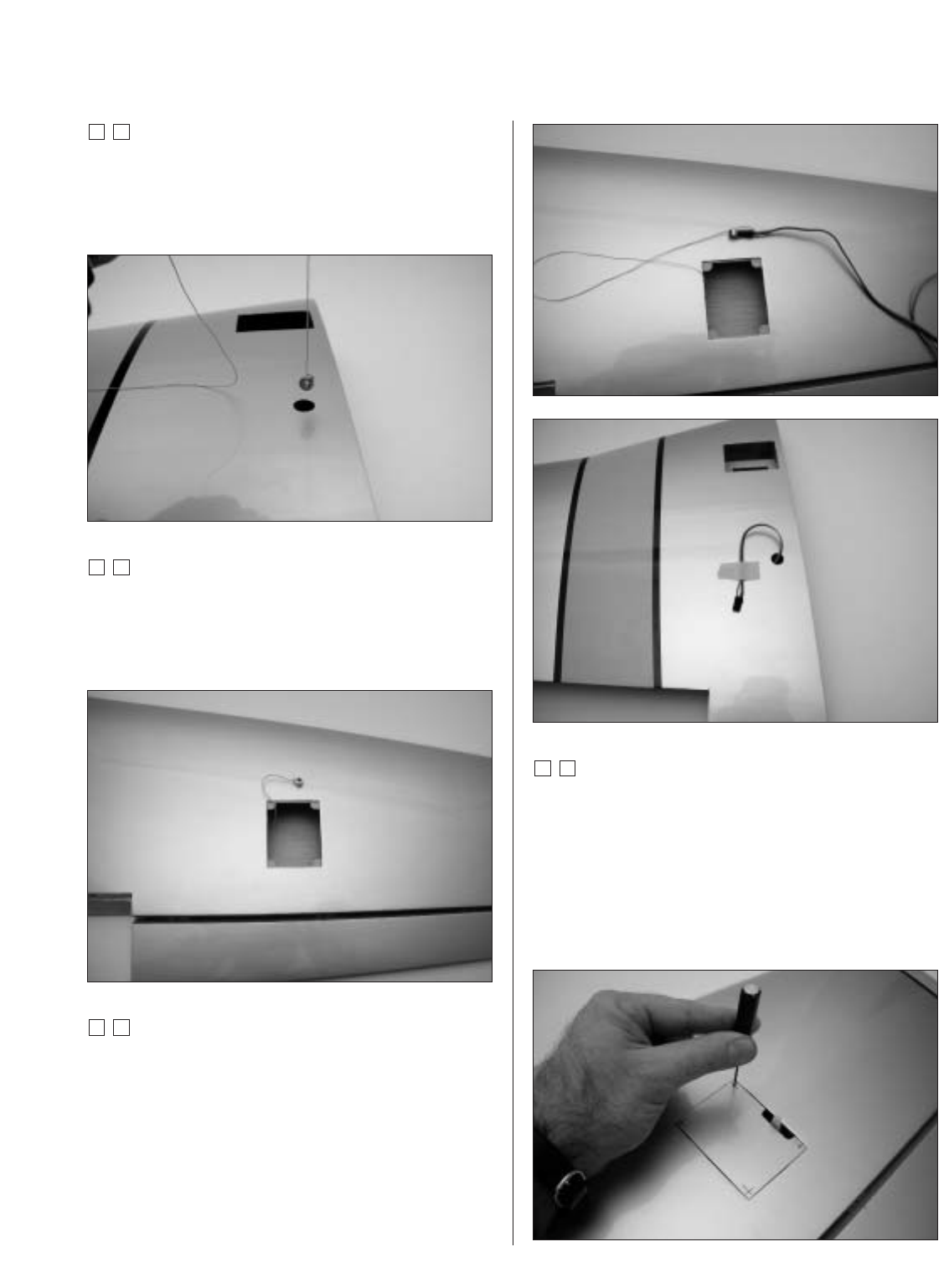
Section 2: Aileron Servo Installation
Step 7
Use a piece of string with a small weight (such as a wheel
collar) attached as a device to pull the servo lead through
the wing. Lower the weight through the opening at the
root of the wing as shown.
Step 8
Stand the wing on the tip and allow the weight to drop
through the wing until it appears in the opening for the
servo leads. It may require a little help to pass by the
wing ribs in the form of slightly shaking the wing.
Step 9
Tie the string onto the servo extension. Gently pull the
extension through the wing using the string. Untie the
string when the servo lead has been pulled through. Use
tape to secure the servo lead to the wing to prevent it
from falling back into the wing panel.
Step 10
Place the hatch cover in position in the aileron opening.
Measure in 1/8" on all four sides of the hatch. Drill four
1/16" holes at the intersections of the lines as shown.
Note: Drill through the servo hatch and the
underlying hatch mounts. Use caution not to
accidentally drill through the top of the wing.
Photo for Step 9
Photo for Step 9