
Specifications


Table Of Contents
- Table of Contents
- Contents of Kit
- Additional Required Equipment
- Additional Required Tools and Adhesives
- Other Items Needed (not included in the kit)
- Warning
- Before Starting Assembly
- Using the Manual
- Warranty Information
- Section 1: Hinging the Ailerons
- Section 2: Aileron Servo Installation
- Section 3: Aileron Linkages
- Section 4: Hinging the Flaps
- Section 5: Flap Servo Installation
- Section 6: Flap Linkages
- Section 7: Retract Servo Installation
- Section 8: Main Landing Gear and Wheel Doors
- Section 9: Joining the Wing
- Section 10: Mounting the Wing to the Fuselage
- Section 11: Lower Air Intake Installation
- Section 12: Stabilizer Installation
- Section 13: Hinging the Elevators
- Section 14: Hinging the Rudder
- Section 15: Tail Wheel Installation
- Section 16: Fuel Tank Assembly
- Section 17A: Engine Installation
- Section 17B: Engine Installation
- Section 18: Throttle Pushrod and Fuel Tank
- Section 19: Radio Installation
- Section 20: Rudder and Elevator Linkages
- Section 21: Throttle Linkage Installation
- Section 22: Attaching the Cowl
- Section 23: Cockpit Details
- Section 24: Attaching the Canopy
- Section 25: Applying the Decals
- Control Throws and Center of Gravity
- Preflight at the Field
- Adjusting the Engine
- 2003 Official AMA National Model Aircraft Safety Code
12
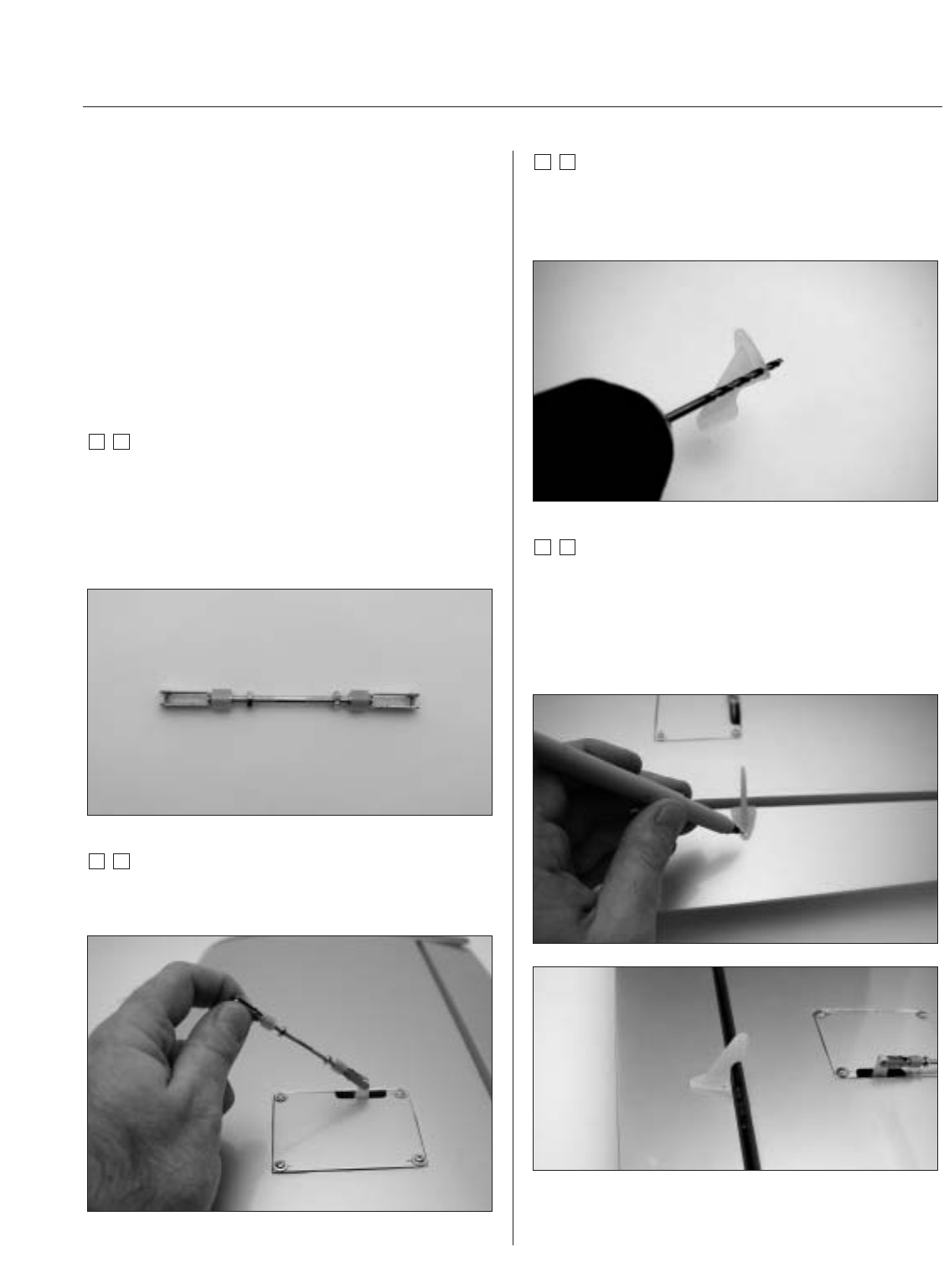
Section 3: Aileron Linkages
Required Parts
• Wing assembly • Control horn (2)
• Mounting screws (6) • Metal clevis (4)
• Clevis keeper (4) • 4-40 x 2" threaded rod (2)
• 4-40 nuts (4) • #2 x 3/8" screws (6)
Required Tools and Adhesives
• Thin CA • Phillips screwdriver
• Drill Bit: 1/16", 5/64" • Drill
• Felt-tipped pen
Step 1
Prepare the 4-40 aileron linkage by placing the clevis
keepers onto the metal clevises. Thread a 2-56 nut onto
each end of the 4-40 x 2" threaded rod. Thread a clevis
onto each end of the threaded rod. The threaded rod
should just be visible between the forks of the clevis.
Step 2
Attach the assembled control linkage to the
aileron servo arm.
Step 3
Remove the back plate from the control horn using side
cutters or a sharp hobby knife. Use a 5/64" drill bit to drill
out the mounting holes in the control horn.
Step 4
Position the control on the aileron by aligning the holes
of the control horn with the hinge line of the aileron and
center on the horn mounting plate (as marked back in
Section 1). Use a felt-tipped pen to transfer the mounting
holes from the control horn onto the aileron.