
Specifications


Table Of Contents
- Table of Contents
- Contents of Kit
- Additional Required Equipment
- Additional Required Tools and Adhesives
- Other Items Needed (not included in the kit)
- Warning
- Before Starting Assembly
- Using the Manual
- Warranty Information
- Section 1: Hinging the Ailerons
- Section 2: Aileron Servo Installation
- Section 3: Aileron Linkages
- Section 4: Hinging the Flaps
- Section 5: Flap Servo Installation
- Section 6: Flap Linkages
- Section 7: Retract Servo Installation
- Section 8: Main Landing Gear and Wheel Doors
- Section 9: Joining the Wing
- Section 10: Mounting the Wing to the Fuselage
- Section 11: Lower Air Intake Installation
- Section 12: Stabilizer Installation
- Section 13: Hinging the Elevators
- Section 14: Hinging the Rudder
- Section 15: Tail Wheel Installation
- Section 16: Fuel Tank Assembly
- Section 17A: Engine Installation
- Section 17B: Engine Installation
- Section 18: Throttle Pushrod and Fuel Tank
- Section 19: Radio Installation
- Section 20: Rudder and Elevator Linkages
- Section 21: Throttle Linkage Installation
- Section 22: Attaching the Cowl
- Section 23: Cockpit Details
- Section 24: Attaching the Canopy
- Section 25: Applying the Decals
- Control Throws and Center of Gravity
- Preflight at the Field
- Adjusting the Engine
- 2003 Official AMA National Model Aircraft Safety Code
20
Section 6: Flap Linkages
Required Parts
• Wing assembly • Control horn (2)
• Mounting screws (6) • Metal clevis (4)
• Clevis keeper (4) • 4-40 nuts (4)
• 4-40 x 1-1/2" threaded rod (2)
• #2 x 3/8” screws (6)
Required Tools and Adhesives
• Thin CA • Phillips screwdriver
• Drill Bit: 1/16", 5/64" • Drill
• Felt-tipped pen
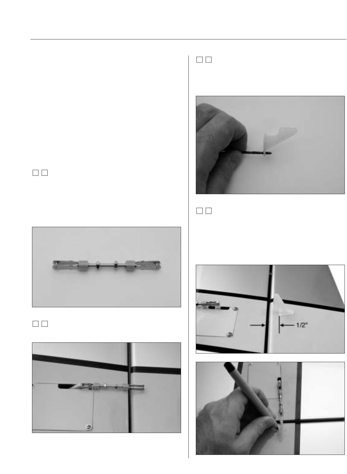
Step 1
Prepare the flap linkage by placing the clevis keepers onto
the metal clevises. Thread a 4-40 nut onto each end of the
4-40 x 1-1/2" threaded rod. Thread a clevis onto each end
of the threaded rod. The threaded rod should just be
visible between the forks of the clevis.
Step 2
Attach the assembled linkage to the flap servo arm.
Step 3
Remove the back plate from the control horn using side
cutters or a sharp hobby knife. Use a 5/64" drill bit to drill
out the mounting holes in the control horn.
Step 4
Position the control horn on the flap by: Aligning the front
edge of the control horn 1/2" behind the trailing edge of
the wing and in-line with the flap control linkage. Use a
felt-tipped pen to transfer the mounting holes from the
control horn onto the flap.