
Specifications


Table Of Contents
- Table of Contents
- Contents of Kit
- Additional Required Equipment
- Additional Required Tools and Adhesives
- Other Items Needed (not included in the kit)
- Warning
- Before Starting Assembly
- Using the Manual
- Warranty Information
- Section 1: Hinging the Ailerons
- Section 2: Aileron Servo Installation
- Section 3: Aileron Linkages
- Section 4: Hinging the Flaps
- Section 5: Flap Servo Installation
- Section 6: Flap Linkages
- Section 7: Retract Servo Installation
- Section 8: Main Landing Gear and Wheel Doors
- Section 9: Joining the Wing
- Section 10: Mounting the Wing to the Fuselage
- Section 11: Lower Air Intake Installation
- Section 12: Stabilizer Installation
- Section 13: Hinging the Elevators
- Section 14: Hinging the Rudder
- Section 15: Tail Wheel Installation
- Section 16: Fuel Tank Assembly
- Section 17A: Engine Installation
- Section 17B: Engine Installation
- Section 18: Throttle Pushrod and Fuel Tank
- Section 19: Radio Installation
- Section 20: Rudder and Elevator Linkages
- Section 21: Throttle Linkage Installation
- Section 22: Attaching the Cowl
- Section 23: Cockpit Details
- Section 24: Attaching the Canopy
- Section 25: Applying the Decals
- Control Throws and Center of Gravity
- Preflight at the Field
- Adjusting the Engine
- 2003 Official AMA National Model Aircraft Safety Code
Section 8: Main Landing Gear and Wheel Fairings
27
Step 11
Position the gear door mounts as follows: Position mount
near the wheel so it is almost touching the wheel well.
Position the mount near the retract mechanism slightly
below the wheel well.
Step 12
Extend the retract. Position the landing gear door so the
centerline and lower edge marks are aligned. Mark the
screw locations for the landing gear door mount screws.
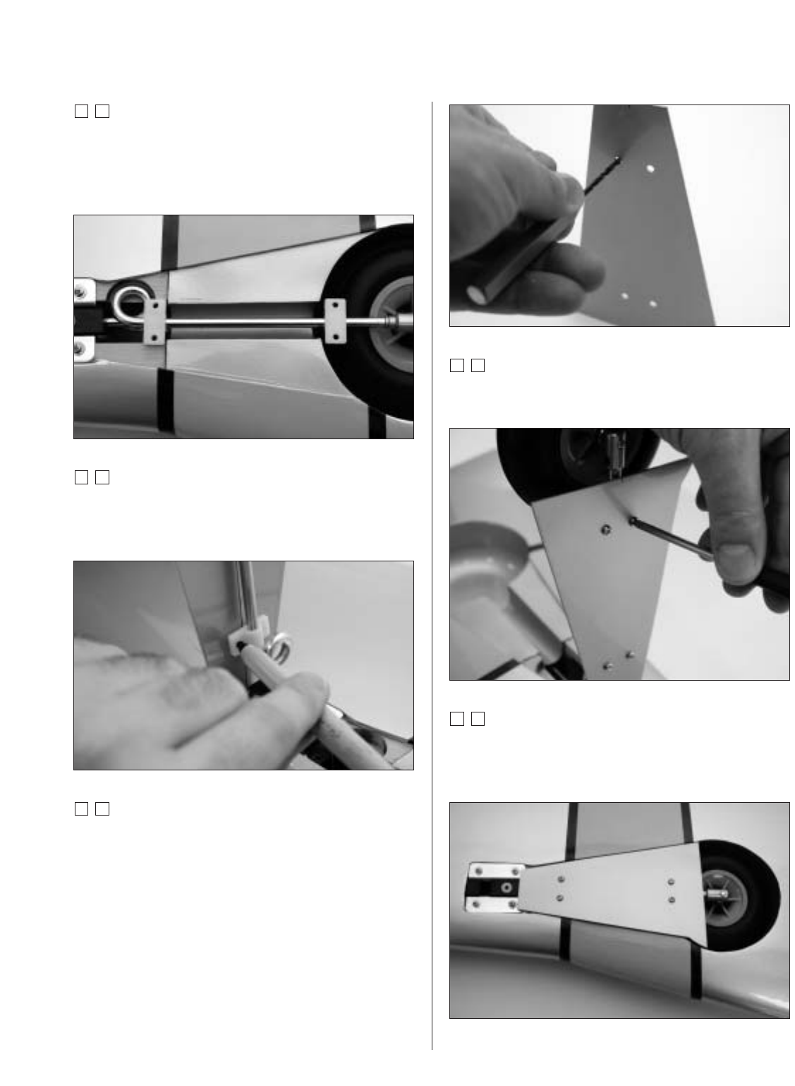
Step 14
Drill the locations marked in the previous step using
a 1/8" drill bit.
Step 15
Secure the landing gear door to the mounting brackets
using four #4 x 7/16" screws.
Step 16
Move the landing gear to the retracted position. Check the
fit of the landing gear door and make any adjustments to
provide a perfect fit.
Photo for Step 14