
Specifications


Table Of Contents
- Table of Contents
- Contents of Kit
- Additional Required Equipment
- Additional Required Tools and Adhesives
- Other Items Needed (not included in the kit)
- Warning
- Before Starting Assembly
- Using the Manual
- Warranty Information
- Section 1: Hinging the Ailerons
- Section 2: Aileron Servo Installation
- Section 3: Aileron Linkages
- Section 4: Hinging the Flaps
- Section 5: Flap Servo Installation
- Section 6: Flap Linkages
- Section 7: Retract Servo Installation
- Section 8: Main Landing Gear and Wheel Doors
- Section 9: Joining the Wing
- Section 10: Mounting the Wing to the Fuselage
- Section 11: Lower Air Intake Installation
- Section 12: Stabilizer Installation
- Section 13: Hinging the Elevators
- Section 14: Hinging the Rudder
- Section 15: Tail Wheel Installation
- Section 16: Fuel Tank Assembly
- Section 17A: Engine Installation
- Section 17B: Engine Installation
- Section 18: Throttle Pushrod and Fuel Tank
- Section 19: Radio Installation
- Section 20: Rudder and Elevator Linkages
- Section 21: Throttle Linkage Installation
- Section 22: Attaching the Cowl
- Section 23: Cockpit Details
- Section 24: Attaching the Canopy
- Section 25: Applying the Decals
- Control Throws and Center of Gravity
- Preflight at the Field
- Adjusting the Engine
- 2003 Official AMA National Model Aircraft Safety Code
34
Section 11: Lower Air Intake Installation
Step 9
Remove the excess tube using a razor saw and
hobby knife.
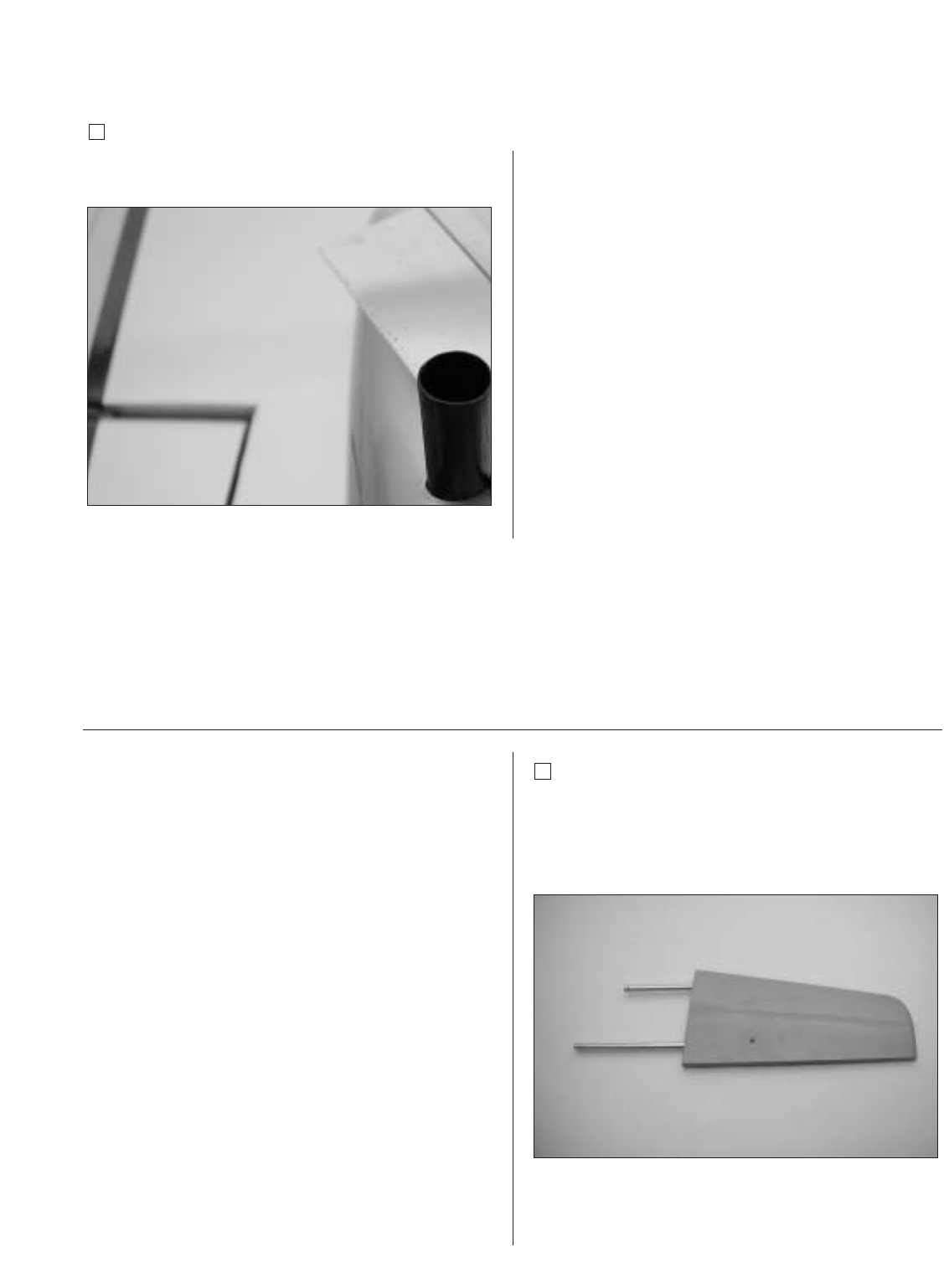
Section 12: Stabilizer Installation
Step 1
Locate both of the stabilizer tubes, short and long. Slide
the tubes into one half of the stabilizer as follows: short
tube towards the leading edge and the long tube towards
the trailing edge.
Required Parts
• Fuselage • Stabilizer (right and left)
• Stabilizer tube (short) • Stabilizer tube (long)
• #2 x 3/8" screw (2)
Required Tools
• Drill Bit: 3/32" • Drill
• Phillips screwdriver